Continue to Site

Welcome to our site!

Electro Tech is an online community (with over 170,000 members) who enjoy talking about and building electronic circuits, projects and gadgets. To participate you need to register. Registration is free. Click here to register now.

  • Welcome to our site! Electro Tech is an online community (with over 170,000 members) who enjoy talking about and building electronic circuits, projects and gadgets. To participate you need to register. Registration is free. Click here to register now.

Need help about a 7805 regulator circuit !

Status
Not open for further replies.
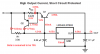
I cobbled together a little simulation in SwitcherCAD for this problem. The values for R1 and Rsc are shown as .params. As was pointed out, this is hypothetical, and doesn't use real parts that you can buy or steal.

Ron
 

Attachments

  • reg_waves.gif
    reg_waves.gif
    11.3 KB · Views: 817
  • current_limited_supply.gif
    current_limited_supply.gif
    11.4 KB · Views: 1,275
Hi Ron,
It looks like your sim is using 0.228 ohms for R2{R1} and R3. Then with 1A through the 7805 regulator the voltage drop across R2{R1} will be only 0.228V and the booster transistor Q4 won't be anywhere near being turned on.
The 7805 must pass 0.6V/0.228 ohms = 2.63A for the booster transistor to begin conducting, and when the booster transistor reaches a collector current of 4A with a Vbe of 1V, the 7805 will have 1.912V/0.228 ohms = 8.39A through it! :(
 
audioguru said:
Hi Ron,
It looks like your sim is using 0.228 ohms for R2{R1} and R3. Then with 1A through the 7805 regulator the voltage drop across R2{R1} will be only 0.228V and the booster transistor Q4 won't be anywhere near being turned on.
The 7805 must pass 0.6V/0.228 ohms = 2.63A for the booster transistor to begin conducting, and when the booster transistor reaches a collector current of 4A with a Vbe of 1V, the 7805 will have 1.912V/0.228 ohms = 8.39A through it! :(
I should have numbered the resistors differently.
{R1}=3 ohms=the value of R2. (.param R1=3)
{Rsc}=0.228=the value of R3. (.param Rsc=0.228)

Ron
 
Hi Ron,
Don't you argee that if {R1} is 3 ohms, and if the regulator has 1A thru it, then the voltage drop across {R1} is slightly less than 3V and your booster transistor Q4 would be turned-on so hard that the other transistor Q3 would current-limit? Then the Rsc would have about 0.9V across it and wouldn't you know, have nearly 4A through it! :shock:

But it doesn't work that way because Vbe of Q4 plus the voltage across Rsc reduces the voltage across the 3 ohms resistor, reducing the current in the regulator to about only 633mA. :lol:
 
Hi Len,

The additional current (1A-633mA=367mA) will flow through Q3, if Q3 is robust enough to carry that current. It might be better to make R2=2.2 ohms, which (in my sim) increases its max current to about 856mA, and reduces the max current through Q3 to about 104mA. You can't cut this too thin without running into component tolerance problems, but then this is just an academic exercise.
If anyone wants to try this, here is the SwitcherCAD file. I have posted it as a text file, because the forum doesn't accept .ASC files. Save it to C:\Program Files\LTC\SwCADIII (or wherever you keep your schematic files) and rename it with the .ASC extension.
 

Attachments

  • scp_reg.txt
    3.9 KB · Views: 243
Hi Ron,
I changed the file type of your sim file before downloading it and got SwCADIII to open your schematic. I watched it run a few things but it is different with R1 = 2.2 ohms.

Do you think the Current limiter transistor is active with a 5A load?
If this is the case then I am giving my appologies to Russ and Morgen. :oops:

Do you think it looks like this:
 

Attachments

  • boosted_lm7805_again_and_again.png
    boosted_lm7805_again_and_again.png
    15.5 KB · Views: 2,027
audioguru said:
Hi Ron,
I changed the file type of your sim file before downloading it and got SwCADIII to open your schematic. I watched it run a few things but it is different with R1 = 2.2 ohms.

Do you think the Current limiter transistor is active with a 5A load?
If this is the case then I am giving my appologies to Russ and Morgen. :oops:

Do you think it looks like this:
Yeah, I think that you were missing the fact that Q2 will conduct when it limits the voltage across Rsc. It will supply the difference between The regulator's current and the current through R1.
 
hi
i need help with designing a power supply of 5v-5a(high voltage,high current).
cant get the current to boost by using a current booster.if u have the circuit diagram even that will do...but not by using a MJ power transistor only current booster
 
hi
i need help with designing a power supply of 5v-5a(high voltage,high current).
cant get the current to boost by using a current booster.if u have the circuit diagram even that will do...but not by using a MJ power transistor only current booster
Sounds like you need a switching regulator.
 
Hi there,


Here's how it all works......


Since Ir1 depends on the two Vbe drops of the transistors just before cutoff:

R1=(Vbe1+Vbe2)/(Ir1-Ic1/B1)

but since Vbe changes we want to allow a 50 percent
change in the two Vbe so we would get:

R1=1.5*(Vbe1+Vbe2)/(Ir1-Ic1/B1)

or

R1=1.5*(Vbe1+Vbe2)/(RegIlimit-Io/B1+RegIlimit/B1)

Since Q2 begins conducting at Vbe2:

Rsc=Vbe2/((Io-RegIlimit)*(1+1/B1))

where

Vbe1 is base emitter voltage of Q1, and
Vbe2 is base emitter voltage of Q2, and
RegIlimit=Regulator I limit
Ic1=collector current of Q1
Io is total output current
B1 is beta of Q1
Rsc is Q2's base emitter resistor
Ir1 is current through R1


Not too difficult?


Numerical example 1:

Io=5 amps
RegIlimit=1 amp
B1=100
Vbe1=1 volt
Vbe2=1 volt

Calculate R1:
R1=1.5*(Vbe1+Vbe2)/(RegIlimit-Io/B1+RegIlimit/B1)
so, R1=3.125 ohms.

Calculate Rsc:
Rsc=Vbe2/((Io-RegIlimit)*(1+1/B1))
so, Rsc=0.248 ohms


Numerical example 2:

Io=5 amps
RegIlimit=1 amp
B1=10 (much lower than before)
Vbe1=1 volt
Vbe2=1 volt

Calculate R1:
R1=1.5*(Vbe1+Vbe2)/(RegIlimit-Io/B1+RegIlimit/B1)
so, R1=5 ohms.

Calculate Rsc:
Rsc=Vbe2/((Io-RegIlimit)*(1+1/B1))
so, Rsc=0.227 ohms


Another point of view is that if R1 goes too low the regulator will cut back too soon, and if R1 is too high Q2 has to do more work.
A good value would be one that always allows Q2 to work, but as little as possible.
 
Last edited:
Mr Al, this thread is over 3 years old. I don't think amazing ang wants to use the circuit that was being discussed. I could be wrong.
 
Mr Al, this thread is over 3 years old. I don't think amazing ang wants to use the circuit that was being discussed. I could be wrong.


Hi Roff,

Well, if he does now he has a good idea how it works :)
Someone else might find this useful too.
I thought it was a little interesting too, seeing as how it would work with other regulators too.
 
Status
Not open for further replies.

New Articles From Microcontroller Tips

Back
Top