Continue to Site

Welcome to our site!

Electro Tech is an online community (with over 170,000 members) who enjoy talking about and building electronic circuits, projects and gadgets. To participate you need to register. Registration is free. Click here to register now.

  • Welcome to our site! Electro Tech is an online community (with over 170,000 members) who enjoy talking about and building electronic circuits, projects and gadgets. To participate you need to register. Registration is free. Click here to register now.

Need help about a 7805 regulator circuit !

Status
Not open for further replies.

Zarkabul

New Member
Hi everybody!
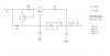
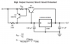
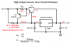
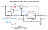
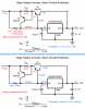
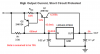
I need some help about a circuit analyse. You can see the circuit in the attachment. It is a 7805 regulator circuit. 7805 part allows max 1A out current, so the circuit is designed again with 2 pnp transistors to get a 5A out current. 4A current flows over the collector of the second transistor. Thus the out current reaches 5A (4A from the transistor + 1A from the 7805). Some information is given in the circuit and the wants are the values of the resistors in the circuit. I couldn't solve it :(. Please could you solve it and tell it to me clearly. And I will be so glad if you tell it over the picture. Thank you for your help.
 

Attachments

  • circuit_952.jpg
    circuit_952.jpg
    17.3 KB · Views: 4,436
T1 is a current limiter. When the current thru T2 reaches 4 amps, you want T1 to turn on. The base-emitter voltage of T1 is 0.6 volts, so by Ohm's Law: R2 = 0.6/4 = 0.15 ohms.

The 7805 needs about 7 volts at the input to work, so the drop across R1 is 3 volts max. R = E/I = 3 ohms.
 
Sorry Russ,
When T2 is conducting 4A, its base-emitter voltage will be about 1V. So R1 should be 1 ohm plus the voltage across R2.
EDIT: R1's calculation.

The power rating of the parts depends on their current that we know, and on the voltage across them, so Pr1 = 4W (use 5W or more) and Pr2 = 2.4W (use 3W or more). We don't know the voltage across the transistors so we can't calculate their power.
 
Thank you for answers Russlk and audioguru, but there must be a certain solution. This problem is one of our final examination problems. The beta values of the transistors given on the circuit should be used for the solution. For instance, for T2 the collector current Ic2 = 4A, the base current Ib2= 4/100 = 0.04 A and the emitter current Ie2= 4.04 A. By the way i've missed to indicate the GND end of the 7805, it will be directly connected to the ground. In other words the referance voltage for 7805 is 0, it's as usual.
 
Your school's examination request is not realistic because you can't buy transistors with a beta of 100 at 4A. Their beta will be within the range of from 20 to about 80. Also, transistors have a range of Vbe that is wide. Therefore you would be crazy to design the circuit with the regulator's current as high as 1A which is so close to its limit.

In National Semi's datasheet, they have the same circuit and use the same 3 ohm current sensing resistor as Russ proposed. But their regulator is operating at a current much less than 1A. They have a detailed formula involving beta so use it. :lol:
 

Attachments

  • boosted_lm7805.png
    boosted_lm7805.png
    16.9 KB · Views: 4,508
Sorry, with a regulator current of 1A, R1 should be 1.875 ohms, if you could find a transistor with a beta of 100 at 4A, and with a Vbe of 1V.
 

Attachments

  • boosted_lm7805_calculation.png
    boosted_lm7805_calculation.png
    18.9 KB · Views: 6,152
Look what happens if you build it with resistors calculated for the transistors having a beta of 100 and a Vbe of 1.0V, but end-up with low spec transistors with a beta of only 20 and a Vbe of 1.2V. The regulator will try to pass 1.25A but won't do a good job and might even shutdown if it gets too hot.
 

Attachments

  • boosted_lm7805_calculation_again.png
    boosted_lm7805_calculation_again.png
    19.8 KB · Views: 5,343
Thank you very much for your expression audioguru :) . I got it clearly, i know the values i've given to you are not certainly realistic, it's just an examination problem and the values are just approach i think. I wanted to get the principle of this event only, but i know more much things now owing to you. I will design better regulators after this time be sure of this :D . Thanks again and good luck!

Suleyman
 
R1 is not essential, its value could be zero and the circuit will still work. R1 reduces the power dissapated in the LM7805, so with 10 volt supply and max load, the dissapation in the 7805 is minimized when R1 = 3 ohms.
 
Russlk said:
R1 is not essential, its value could be zero and the circuit will still work.

If R1 is zero ohms, then Q1 could never turn ON (as it's base and emitter would be shorted together), so the 7805 would provide all the current, limiting it to the 1A maximum of the 7805.

So without R1 the circuit wouldn't work!.
 
Russlk said:
R1 is not essential, its value could be zero and the circuit will still work. R1 reduces the power dissapated in the LM7805, so with 10 volt supply and max load, the dissapation in the 7805 is minimized when R1 = 3 ohms.
The power dissipation in the 7805 is reduced when it has a low current, so R1 must have a high value. Allowing for only 10mA through R1 at full output to bypass leakage current in the boosting transistor, R1 = 169.8 Ohms.
 

Attachments

  • boosted_lm7805_comparison.png
    boosted_lm7805_comparison.png
    39.8 KB · Views: 1,559
If this were a gambling site, my money would be on Russlk.
This is a hypothetical circuit, so I'm boggled by the whole of responses.
"When T2 is conducting 4A, its base-emitter voltage will be about 1V."
(How was this 1 volt Vbe determined?)
"The power rating of the parts depends on..."
(The problem is to solve for the resistor values.)
"If R1 is zero ohms, then Q1 could never turn ON (as it's base and emitter would be shorted together)"
(Has R1 in the original circuit has been confused in the NS circuit?)
"The power dissipation in the 7805 is reduced when it has a low current, so R1 must have a high value."
(The current through the 7805 is 1A.)
 
Morgen said:
"When T2 is conducting 4A, its base-emitter voltage will be about 1V."
(How was this 1 volt Vbe determined?)
Any power transistor has a high Vbe when it has 4A of collector current. I couldn't find a datasheet for the ones in my example, but a common 15A-rated 2N3055 power transistor has a max Vbe of 1.5V at 4A.

"The power rating of the parts depends on..."
(The problem is to solve for the resistor values.)
Patrt of the excercise was to calculate power dissipation of its parts. I missed seeing a 10V input voltage in my 1st reply.

"If R1 is zero ohms, then Q1 could never turn ON (as it's base and emitter would be shorted together)"
(Has R1 in the original circuit has been confused in the NS circuit?)
The circuits are identical.

"The power dissipation in the 7805 is reduced when it has a low current, so R1 must have a high value."
(The current through the 7805 is 1A.)
No it isn't. The current through the 7805 depends on the value of R1 and on the Vbe of the booster transistor.

If R1 is 3 ohms and the Vbe is 1V, then the 7805 passes only 644mA and you lost your bet. :lol:
 

Attachments

  • boosted_lm7805_again.png
    boosted_lm7805_again.png
    15.7 KB · Views: 1,395
Hi Audio,

About the value of R1, I sort of reckon the 7805 should reach its full load current of 1A when the excess is taken up by the boost transistor.

So if I design a 4.5A supply, the current distribution would be 1A via 7805 and 3.5A via boost transistor. For a 10A output, 9A via the boost transistors.

With the 7805 mounted along with the transistors, its thermal protection would take care of my boost transistors too. That's my view. Any comment.
 
Status
Not open for further replies.

Latest threads

Back
Top