Continue to Site

Welcome to our site!

Electro Tech is an online community (with over 170,000 members) who enjoy talking about and building electronic circuits, projects and gadgets. To participate you need to register. Registration is free. Click here to register now.

  • Welcome to our site! Electro Tech is an online community (with over 170,000 members) who enjoy talking about and building electronic circuits, projects and gadgets. To participate you need to register. Registration is free. Click here to register now.

My Workshop Equipment

Status
Not open for further replies.

Musicmanager

Well-Known Member
Hi Guys

As a complete novice I'm currently in the business of equipment aquisition to compliment my new found knowledge ! Well, knowledge ? I've already found it's easier to collect the gear than to the knowledge to know when and how to use it but I'm getting along OK, mainly thanks to you guys !

I have a 'Scope, a Freq. Gen, a Freq. Meter, several Multimeters and a Component Tester, all the usual handtools and a soldering station. I'm currently building a PSU with a variable 0 - 30v @ 3amps and 5v & 12v discreets which is a project I've developed with considerable help to get to the building stage.

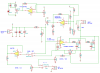
My next equipment project is a Variable Constant Load and I'd like your opinion of the scheme detailed below. There are some elements I have already concluded to change related to how the unit is powered but there are some elements of the construction I don't yet understand so I'm unable to access the viability ie I thought a Varistor made good coffee at Costa ?

The link to the website page is **broken link removed**

and the schematic is posted.

Thanks Guys

S
 

Attachments

  • schematicrev4.png
    schematicrev4.png
    36 KB · Views: 221
I'd be a bit suspicious of the 2 paralleled mosfets. They may well balance out the load as their Igs changes due to heating, but every fibre of my being screams out to put in balancing resistors. These two will give you a combined max current capability of 100A if the transistors stay cool, however once they heat up that capacity will go down - the datasheet says 35A at 100C, so that would be 70A combined. Personally I think I'd just use one tranny and build a much "lighter" load.

I'd also question that 0.1R sense resistor. You need to make sure it is up to the current this thing can handle. Same goes for the wiring and panel sockets, it all looks a bit lightweight, so (and someone please correct me!) what's the point of a 100A pass element when the wires connecting it are going to melt?
 
Hi Throb

Thanks for your information, much appreciated. I will need to read through and think about what you've said a number of times before it totally makes sense to me - dementia, you know - however, I did recall reading on the webpage .. ..

'In this design, the maximum current should be about 7A and it is limited by the 5W resistor I used; not by the MOSFETs. Larger currents can be achieved with a resistor capable of 10 or 20 W dissipation (which I didn't have handy). The input voltage should not exceed 60V (maximum VDS for these MOSFETs). As an added protection measure, I added a power MOV from the input to ground to protect the MOSFETs against high-voltage transients.'

At the moment I'm not sure if this is answering your concerns or not but to add to concern, I'm not sure I want to build something capable of 100A for m y own safety. May well be safe in experienced hands but, meanwhile fried MM ?

S
 
I never noticed that, and didn't think of it for myself either - shame on me! I hadn't actually read much of the text, and wrongly assumed the paralleled mosfets were to increase current capability, when in fact they are to decrease the combined "on" resistance. Oops... With a 0.1 ohm sense resistor it would need a rating of 1000W to be able to pass 100A. Well that's never going to happen. I am a dumass...

Anyway, no need to worry about safety aspect of something capable of handling a large current, apart from its ability to get hot. It's not the excessive ability of a device to cope with extremes you have to worry about, it's the extremes themselves, and inadequately rated components.

Ok, quick calculation. The article talks about 7 amps because the 0.1 ohm resistor is rated at 5W, so I'll use that. The mosfet in use has an Rds(on) of 0.022 ohms. So with 2 in parallel, that's 0.011, put 7 amps through that, you get 7x0.011=0.077 volts. With only 1 transistor, you get 7x0.022=0.154 volts, and only 1.078 watts of power dissipation (and only 0.539 for the 2 transistors in parallel). So the question becomes, under what circumstances are you going to want to load something where the voltage is that low? The only thing I can think of is foldback current limiting of a PSU - ok so it might be handy if you design psu's... But even so, you have to remember there is a 0.1 ohm resistor in series anyway, which at 7 amps is going to drop 0.7 volts, effectively swamping the voltage dropped by the mosfets.

Supposing you want to test a 12 volt PSU, rated at 3.5amps, with a 3 amp load. That gives you 36 watts which your load has to dissipate, and it has to set it's mosfets to have a resistance of 4 ohms (well ok, 3.9 because you have the sense resistor in series) - way above the low combined Rds(on) you get with this design. But suppose you crank the load so it now draws 4 amps. If the PSU has foldback current limiting, the voltage will drop right down, and depending the design it may sustain that amount of current or it may pop a fuse, but what should happen is that the voltage drops down enough that the constant current load reaches it's minimum resistance, so only 3.5 amps is delivered. Foldback is conceived with the idea of constant resistance loads, where if the voltage is dropped down, at some point the current will fall within the design limit of the supply.

Hope this clears some things up a bit :)
 
Hi Throb

Thanks for taking the time to go through this with me, much appreciated.

As for the safety aspects, whilst I appreciate that for the Constant Load the only real issue is heat dissipation it does also mean that it is connected to something capable of supplying 100 amps. I don't think I want something that powerful on my bench.

The calculations are great information and amazingly I understand them and also the likely outcome of the circuit in use as a result.

My next step is a twofold I think. Firstly, I'd like to play around with the calculations with different values so that the analysis procedure sticks with me and secondly, I clearly need to do more research into Mosfets, balancing resistors etc

When I've done that, I'll have a go at revising the schematic and perhaps I could then seek your further thoughts

Thanks again
S
 
Great!
I just re-read your first post. Whilst Costa do make very good coffee, it's a barista that does it! I suppose they might stir it with a varistor for you if you ask them nicely...
 
If you have a 20W sense resistor, you would get a max current of 14.14A, more than enough for most people. The resistor would be dropping 2V, if you had a single mosfet it would be dropping 0.3V and dissipating 4.3W. So anyway, the resistor would need a lot more cooling than the transistor.

I did a quick search for constant current loads and found this: https://electronicdesign.com/displays/resistive-dummy-load-draws-constant-current-12-50-v it's worth a look to compare the design. Personally I think this one is much better, though you don't have the fancy extras. You could change the mosfet for the one used in Paulo's design though.
 
Hi Throb

Whilst Costa do make very good coffee, it's a barista that does it! I suppose they might stir it with a varistor for you if you ask them nicely...

My wife would happily confirm that I need no help stirring it !!

Thanks for the electronic design link - I'll add that into my research equation and get back at a later date.

Regards

S
 
Lol :) It's often good when getting to grips with a type of circuit you are not familiar with, to start with the simplest version you can find, understand how it works, then try to understand the changes other people have made - that way you can make informed decisions about the value of those changes, and also be able to easily distinguish between the core functionality of something, and "frills" when trying to understand what's going on. It also gives you a good starting point to come up with your own version. Often it's the case that a good design can be ruined by ill considered "enhancements". OTOH, well designed enhancements can make a world of difference to how useful something is. Take Dave Jones' constant current load, on which Paulo's is based. It's a simple, reliable design, and a really good illustration of how they work, great for occasional use. But it does nothing to help you use it more easily, and can't be credited with great precision - though you probably don't need that anyway. Swings and roundabouts.

Oh BTW the ED link is dated 2001 - there will be better components around now!
 
Hi Guys

Thanks for all the information, I really need to do some serious research now.
One question, several of the schematics you've highlighted show a component marked 'TVS' but I can't find any reference to it in my books - what is it ?

Thanks
S
 
I don't understand how these fancy load projects are better than a fixed resistor or a power rheostat for loading a power supply for low frequency testing. What am I missing?
 
Constant current, my friend, adjustable constant current! A power rheostat is an expensive thing, and fixed resistors are rather limiting in the values and power ratings you happen to have, and not something you want to have to keep buying just for tests.
 
"adjustable constant current"
That's what I was missing. As you change voltage the load changes to keep a constant current.
A rheostat may do that, in a way.

Buying new power devices is expensive.
 
"adjustable constant current"
That's what I was missing. As you change voltage the load changes to keep a constant current.
A rheostat may do that, in a way.

Buying new power devices is expensive.
A rheostat doesn't do that in any way automatically, its just a power variable resistor...you still need to manually adjust it.

Adjustable electronic loads have the benefit of cutting down the testing time of a power supply dramatically. Think about how easy it makes efficiency testing just for one thing.

The commercial ones you can buy are also generally programmable from a PC, and can step between different loads, change between constant current/resistance/power. Meaning you can do min-max load conditions several times over, stress testing your power supply and its regulating, overshoot and ripple characteristics.

The time saved using one of these easily outweighs the cost.
 
"A rheostat may do that, in a way."
It is adjustable. So what if it is not automatic? The OP is a hobbyist.
He is not a test technician or engineer dealing with a production run every day.
He wants to be able to provide a load to things he builds.
He can test at .5A, 1A, 5A, 10A, .... He does not need to do the next power supply in 10 minutes.
 
Yep, it's easy for the pro's here to forget that us amateurs usually have far simpler needs than they do ;)
 
"A rheostat may do that, in a way."
It is adjustable. So what if it is not automatic? The OP is a hobbyist.
He is not a test technician or engineer dealing with a production run every day.
He wants to be able to provide a load to things he builds.
He can test at .5A, 1A, 5A, 10A, .... He does not need to do the next power supply in 10 minutes.
Yep, it's easy for the pro's here to forget that us amateurs usually have far simpler needs than they do ;)
Heh, I was just listing some benefits.

Just because a hobbyist doesn't particularly need one, doesn't mean he wont benefit from having one. Making life a little easier shouldn't be exclusive to 'pro's' either. Its a little patronising to think, "well, you're a hobbyist, rather just solder/desolder loads of resistors".
 
It's fun to make the complicated feature-full stuff too :)
 
Status
Not open for further replies.

Latest threads

Back
Top