kinarfi
Well-Known Member
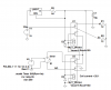
As I looked the drawings and the sims for the relay flip flop, I noticed that the 6 volt relays get 12.6 volts applied while the toggle signal is being applied every other time. If the toggle signal is applied for an extended time, the relay may fail due to over voltage. I have some 5 volt relay that I plan to use to build a flip flop with and to prevent them from being over voltaged, I plan to add an lm317 to limit the current to the amount that one relay would draw at the correct voltage. The sim says it will work.