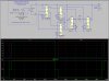
The sim is likely running to completion. Are you then clicking on a circuit node to display the voltage in the plot pane?Mike,
I changed the diode to MURS120 but when I try to simulate it, it won't do anything. I am not getting any error either.
Continue to Site
")