Electro Tech is an online community (with over 170,000 members) who enjoy talking about and building electronic circuits, projects and gadgets. To participate you need to register. Registration is free. Click here to register now.
Welcome to our site! Electro Tech is an online community (with over 170,000 members) who enjoy talking about and building electronic circuits, projects and gadgets. To participate you need to register. Registration is free. Click here to register now.
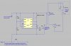
The link in post #27 is invalid. Can you repost? BTW, the pot is there to adjust the time for which the solenoid is energised, to allow for the current to build up in the coil and for the solenoid to pull in. The lockout time is determined by R1C1. R2 is there only to limit discharge current through the switch, to prolong the switch contact life. It has nothing to do with the timing and its value is non-critical.
Why is the distance between the 1st and 2nd pulse always larger than the 2nd and 3rd.
Considering my config I should just be able to ground your trig as the circuit is only powered by my trig closed.
Also, do you think I should put a diode on the +5v connected to ground?
Ive update the following link with an inductor used as the relay but still cant run it in the sim. **broken link removed**
I removed the trigger and r1 from your original post alec-t and when running 250k pot at 180 its gives me a one shot pulse of.2 seconds upon power up. **broken link removed**
So everything should work fine im gathering, i received the nMOSFEsS today, logic level ones,
as soon as i look thru the data sheet and find the pinouts for the nMOSFET ill solder it in and give it a go.
Sorry, my bad. I hadn't checked your asc file when I replied about the relay simulation. Ignore that reply.
I'm afraid your config in the post #31 link won't do what you want as you have trig grounded and the relay isn't simulated accurately.
The FET does the switching of the solenoid, making a relay unnecessary. You could use a relay instead of the FET.
Why is the distance between the 1st and 2nd pulse always larger than the 2nd and 3rd.
That's just because of the way the sim is set up with a 0.2sec delay on the simulated trigger pulse. You can easily alter that if you wish. At power-up the 555 circuit is triggered, causing a spurious activation of the solenoid. That could be prevented by adding suitable components to the Reset input of the 555 if necessary.
Attached is a revised asc file for a circuit which I think should meet your needs.
I havent checked your new sim but i wired everything up as id shown in my last post, removing the trigger resistor and such. wired the fet and relay and tuned the pot to 90k and its working with the solenoid perfectly.
70k is where i start to get into problems.
Last night while i was bored of waiting for the fet i wired only the relay to the solenoid, no ne555 or anything else.
I knew this would keep the solenoid engaged but i just wanted to test out the relays really. They have an led indicator which helps.
While i was testing i found that the relay had some kind of interference with the guns optic. Rapid firing seemed to throw the target off screen.
Maybe something was playing around with the +5 feed i am getting off the optic.
But during my tests tonight everything has run perfectly. Do you think keeping the fet is a good idea to keep the interference away?
I know this doesn't simulate properly but its the most accurate way for me to show you what Ive done.
**broken link removed**
Thanks again for your help alec, when ive got some good lighting ill show you what youve helped me create.
This will help alot of arcade and gaming guys out there.
If you're determined to use a relay then you must have a reverse-biased diode connected across the relay coil (the same way as D1 is connected across the solenoid coil) to prevent damage to the FET, and spurious effects, caused by the back-emf generated by the relay coil inductance when the relay switches off.
This site uses cookies to help personalise content, tailor your experience and to keep you logged in if you register.
By continuing to use this site, you are consenting to our use of cookies.


 Ignore that reply.