Continue to Site

Welcome to our site!

Electro Tech is an online community (with over 170,000 members) who enjoy talking about and building electronic circuits, projects and gadgets. To participate you need to register. Registration is free. Click here to register now.

  • Welcome to our site! Electro Tech is an online community (with over 170,000 members) who enjoy talking about and building electronic circuits, projects and gadgets. To participate you need to register. Registration is free. Click here to register now.

Modified sinewave inverter - protection methods?

Status
Not open for further replies.

mab2

Member
Hi all,

I received lots of good ideas when I asked for help on my dump-load inverter (which is still going strong without blowing fets anymore (thanks again everyone :D )).

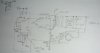
Now I'm building a MS inverter based on a big transformer I've managed to acquire; standard push/pull center-tapped trans setup, and I am hoping I'll be able to use it to drive inductive loads.

I've got snubbers from the fet drains to the center-tap, and MOVs and a snubber on the output of the transformer, and the SG3525 that's driving the fets is limited to about 80% duty cycle, but I was wondering if I should have something more to protect the FETS?

If I've understood correctly, when the fets turn off and current is still flowing (due to the inductive load (e.g. fridge) ) the body-diodes of the fets will conduct, limiting the voltage across the fets, but I wondered if it was safe to rely on this or if I should have additional diodes from the battery -ve to the fet Drains (i.e. parallel to the body diodes?

Or any other ideas?

The battery is 24v nominal; the fets are in parallel banks of four for each side of the trans, and they are rated 100V, 100A each.
 
A schematic would be helpful but assuming what you are saying by push pull the body diodes will not be doing much in this configuration. In and H bridge they would be working like you want but not so much here.

Also given the nominal 24 VDC power source each of your switching devices will be seeing a 2X peak voltage when ever the opposing switching devices are on, assuming that there are no spikes going above that which in some load conditions could very well happen.
Granted you do have a 100 volt rating on your devices so you have a roughly 2X headroom which is good.

In most typical typical push pull switching circuits all that is used for spike snubbing is a simple RC filter going across the two ends of the primary winding.

Now being that you are intending to use this as a power inverter at normal line frequencies you can improve the efficiency a bit by adding a power factor correction capacitor across the secondary side to help filter your waveform into something that is closer to a sine wave.
 
Thanks; I'll try and cobble up a schematic to be sure we're on the same wavelength...

I don't suppose there's a simple rule of thumb method of sizing a PFC cap? (there will be a cap on the motor, but that's the motor run cap and probably doesn't do much for PF)?
 
OK here's the schematic - hopefully it's right.

A schematic would be helpful but assuming what you are saying by push pull the body diodes will not be doing much in this configuration. In and H bridge they would be working like you want but not so much here.

See, I'm not sure that's right - when both sides are off and the load is trying to drive current through the trans the voltage induced will rise to 2x battery on one side (set of fets), but the thing that stops the voltage rising to more than 2x battery is that the other fets drain goes below 0v and the body diode starts to conduct?

At lease that was what I was thinking.
 

Attachments

  • msw1.JPG
    msw1.JPG
    56.1 KB · Views: 1,413
I see. Good point. You may be right and it probably isn't a problem.

Can you get your SG3525 to run reliably at 50 - 60 Hz?

Some can and some can't or at least not without being externally clocked off of a 555 or other timer source first.
 
by 'isn't a problem' I construe that the body diodes can handle the current OK? - so as long as the heatsink is adequate (they're on huge, thick, ally heatsinks BTW)?

I tweaked the frequency to 50.1Hz after setting the 'deadtime' resistor on the workbench, and it seemed stable (c=82n, R=190K and Rdeadtime=5K6); but when I was running it alongside an on-grid transformer the next day, the hums of the two trans' where phasing in and out on a 2 second cycle, suggesting 0.5Hz disagreement (?). This is sufficient for me ATM. If, one day, I want to run clocks and the like off it, I'll think about a crystal referenced clock.

TBH, the next step for me is probably a sinewave driver, possible based on a microcontroller (was reading one of the other posts by RowanBlack (? IIRC) and his PIC based 60/50Hz converting inverters and was wondering how they might scale-up to KW size. Or maybe I might try an do the Trace SW multi-trans setup (but that would be tricky)).

For now I just want something big enough to drive the big freezer(s) (& maybe some old type fluorescents) when the sun's shining :) .

cheers

m
 
Hi mab2,

Good to know you're building the inverter and the fet bank looks adequate...But...go for the full bridge....no spikes, no snubbers, just pure power....in fact the battery becomes the snubber and takes back all that is not needed from motor !...like it ?

Large induction motors always should be driven by a full-bridge inverters, rather then push-pull.
 
Last edited:
hello Zyngame,

the plan is to make a true sinewave inverter using a full bridge, eventually.

As for full bridge with the MSW, I assume that the advantage of full bridge is that when you're outputting 0v (as opposed to +ve or -ve) you can use the bridge to 'short' the transformer? But I would need to use something other than the SG3525 to drive the bridge.

In theory (if I understand correctly) with the push-pull cct i'm using there's no way to short the trans between 'push' & 'pull' but if the load is driving current through the trans it will still use the battery as a snubber/dump by driving one of the fets -ve until the bodydiodes conduct.

IIRC good MSW inverters have a shorting cct to short the trans between push & pull to improve efficiency, but I was thinking that by the time I've done that I've only got a bit further to go to get truesine.
 
Hi mab2,

Another advantage of H-bridge is that the fets see only Vbat as the max voltage stress.
All transients and spikes go straight to the batt or the bridge decoupling capacitor. Whereas If you short the trans primary, the energy is actually wasted
in heating the primary, it doesnt go back to the batt. For PP the scheme works for low power inverters, but for like you want to run a compressor motor, the only
solution is the H-bridge.

The drive to H-bridge is with a dedicated chips.
 
well the fets do see 2x vbatt in PP it is true. That's why I opted for 100v fets to give me plenty of headroom

I thought the only advantage of Full bridge was that you can short the Trans (well that & only subjecting the fets to Vbatt) - shorting the trans means that the load (motor) sees 0v when the PP fets are off so it retains it's energy - rather than feeding it back to the battery through the inverter - that's why shorting the trans is supposed to waste less energy 'cos otherwise you are alternately feeding energy to the motor then taking it back into the battery, on every 1/2 cycle. At lease that's what I read somewhere.

even with the PP, any back current from the trans goes back to the battery, so there's no more wastage than in the full bridge (actually less wastage, in theory, as the current only has to go through one bodydiode cf two in the full bridge).

Or am I missing something?
 
What you have to look at is the state of residual flux in the trans after end of an active PWM pulse, ie during the deadtime. The sec current (motor current ie) and pri flux interact in opposite phase in this period, and whatever topology inverter, it must absorb or dissipate the stored flux (its back emf ie). Experience shows that for larger motors, the bridge works best, due to the fact that it is also a "full-bridge" rectifier connected point-by-point in parallel to an "H-bridge" inverter !!!....got that ?

Secondly, the absence of snubbers, which btw have to be quite hefty (24V pp easily see 200v spikes, under load) otherwise completely useless and fragile, make the H-bridge very very attractive for the motor applications, etc or other inductive loads. Remember, unless you dissipate quite a few watts (15w or so per pp leg, tot 30w), snubbing is futile.

So no question of extra 2 fets in H-bridge and their 0.6V x Itrans power, etc, etc.

In the H-bridge due to its rectifying action at primary side, no matter what the outcome of the pri-sec flux interaction, the resultant emf always gets easily free-wheeled, and thereby returned to the reservoir for next pulse !

Hope you will appreciate, Thanks

(We are in this area of design and manufacturing since 1992)
 
Status
Not open for further replies.

Latest threads

New Articles From Microcontroller Tips

Back
Top