Electro Tech is an online community (with over 170,000 members) who enjoy talking about and building electronic circuits, projects and gadgets. To participate you need to register. Registration is free. Click here to register now.
Welcome to our site! Electro Tech is an online community (with over 170,000 members) who enjoy talking about and building electronic circuits, projects and gadgets. To participate you need to register. Registration is free. Click here to register now.
the only problem i think i might have with just using a voltage devider is that the 12v battery feed has lots of spikes ect on it, do i just need to add a zender diode into the devider circuit or will that not work in a voltage devider circuit
i'v never used attenuator or filter circuits, can you recommend any good web sites to learn about them, the electronic book i read talked alittle about filters but most of it went in and back out again. but iv never even heard of attenuator.
The problem with using a potential divider on car sensors is that it can alter the characteristics of the original sensor.
For example a Vauxhall GTE temperature sender has a resistance of 3410 ohms at -10 degrees and 2030 ohms at 0 degrees. The PIC requires around a 2k input to the A2D converter (well the 18F series do) so your potential divider is going to have to be something like a 1k+2k resistor. This will effectively halve the sensors resistance at -10 degrees leading to a misreading.
For measuring battery voltage this isn't an issue at all but for some of the more sensitive sensors it could be.
Which was why I specifically mentioned that reason - if it's for a high impedance source then simply use a higher value potential divider followed by a buffer (as my tutorial hardware does).
Which was why I specifically mentioned that reason - if it's for a high impedance source then simply use a higher value potential divider followed by a buffer (as my tutorial hardware does).
Actually thats how I've designed the input stages for one of my new products.
High resistance voltage divider for the input stage on a 1/10 divider giving me an input to an LM358DT opamp ranging from 0-1.6 volts (typical vehicle voltage range) and an X2 gain on the opamp giving me out a 0-3.2v output from the LM358DT running from a supply of 5V. The LM358 will not give out any more than around 3.5v from a 5v rail so thats the PIC protected. It will also handle up to 30v on its input pins with a 5v supply (confirmed by ST) so any spikes on the system up to 300 volts will not kill the opamp. Output from the opamp to the PIC is Opamp -> R -> C -> R -> PIC to smooth out any nasty little glitches.
Jason - I've just had a quick browse of Nigels tutorials to see if I could find the circuit he was talking about above - you should be able to use it as it is for what you want to do.
woow, its gona take me a bit of time to work out how that circuit is working.So is that the sort of setup i would have to use on the sensor inputs so not to interfear with the signals goin back to my ecu.
im guessing that as the opamp should not be putting any load on the signal
thanks for all this help, its alot harder than i fault it would be but im learning alot from it and its even giving me more ideas for different projects.
i may have fault of one problem, The MAP sensor. The signal from this is gona be very messy because its measuring vacuum and pressure in the engine.when there is a vacuum in the engine its not constant as the pistons are goin up and down so i guess i could end up with a lot of voltage changes very quickly, high frequancy i guess. will this be a problem
i maybe stupid but i dont understand what the 7660 is really doing, i get the voltage divider before the opamp and the resistors to adjust the gain but what the hell is the 7660, why is it only going to channel 0 opamp. is it coz both opamps are in one ic.
i think im missing something about opamps, i can under stand needing negative when using them with ac but why do you need negative on dc. maybe i should give up,doin my brain in.
The 7660 gives a negative rail for the opamp - this is so it can swing fully to zero, opamps don't swing completely to either power rail (even so called 'rail-to-rail' ones) - by using the 7660 and a 2.5V reference voltage, it gives full and accurate swing from zero volts to maximum.
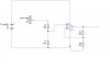
iv attached a circuit that i made from info in one of the last posts by picbits, iv not added any filters yet but is this the right sort of idea. i under stand that the opamp will never go above 3.2 volts so the pic is safe.
does it need a filter after it, ie resistors and caps.
iv attached a circuit that i made from info in one of the last posts by picbits, iv not added any filters yet but is this the right sort of idea. i under stand that the opamp will never go above 3.2 volts so the pic is safe.
I only put the filter after the opamp so I interfere with the input signal as little as possible. Some of the crankshaft/camshaft sensors use a high frequency drive to them so I'm a little wary about putting any capacitance on thats side of the opamp.
In practice it probably wouldn't affect them too much but as I'm desigining stuff for use on customers cars I wouldn't want to take the chance.
This site uses cookies to help personalise content, tailor your experience and to keep you logged in if you register.
By continuing to use this site, you are consenting to our use of cookies.