Continue to Site

Welcome to our site!

Electro Tech is an online community (with over 170,000 members) who enjoy talking about and building electronic circuits, projects and gadgets. To participate you need to register. Registration is free. Click here to register now.

  • Welcome to our site! Electro Tech is an online community (with over 170,000 members) who enjoy talking about and building electronic circuits, projects and gadgets. To participate you need to register. Registration is free. Click here to register now.

MAX712 NiMh battery charger problem

Status
Not open for further replies.

touzenesmy

New Member
Hello everyone,

I hope you'll take few seconds to think about my problem, I actually did some troubleshooting.

I just made a design for Max712/713 battery charger to charge a 2cell NiMh battery

Input voltage is 6V, I took an MJD210 as mosfet.

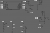
Please find the design in the picture below.

Problem: Upon powering up, even without batteries, the fast charge led is lit, which is abnormal.

I then checked the voltages on the Max712 pins, and here are the abnormal values that I found:

Vref = VLIMIT = 3.4V
THI = 3.11 V
TLO = 3.4V
TEMP = 3.4V

Those values are fixed whenever the Resistors RTH, R3 R4 R5 R6 R7 are connected or not, and batteries connected or not.

However I connected the batteries and charge works, I got the expected 400mA current flow through the Mosfet and 2mA draw to VDRV pin.

However the charge doesn't stop when batteries are charged, so DV/Dt and DT/Dt doesn't work.

I tried this with several chips and different PCBS, can you please help me ?
 

Attachments

  • NiMhCharger_1.1.png
    NiMhCharger_1.1.png
    67.9 KB · Views: 245
A word of advice, many of the posters on here are at the higher end of the age scale so black on grey is not a good combination for a schematic.

Mike.
 
Here's a geriatric-friendly version :)
Changed.PNG
 
Double-check that the ground connections to R4 and R7 are good.
 
First of all, thank you all for your replies !

I just double checked, and yes those connections are good.

As said earlier, the problem is there with, or without resistors RT1 R3 R4 R5 R6 R7...
 
And I'm using those colors mostly because eyes will get less tired of looking at the screen, especially when working at night :)
 
The datasheet says that ref is a 2V output but you are seeing 3.4V. How is it getting to 3.4V?

Mike.
 
The datasheet says that ref is a 2V output but you are seeing 3.4V. How is it getting to 3.4V?

Mike.
That's the question I'm asking myself actually, I guess it's getting it internally, and I can't explain why it's not regulated to 2V
 
Did you buy the ICs from a reputable distributor, or some anonymous online source ?
 
Did you buy the ICs from a reputable distributor, or some anonymous online source ?
Both

Even with the Mouser ones I have the same problem.

Can you isolate the ref pin and check it's voltage?

Mike.
Good idea there

VREF voltage = 0.45V
VLIMIT voltage = ~3V

What ?, isn't Vlimit an input ?...

Led is still on with the trace cut (between VREF and VLIMIT), which means that device is in fast charge mode.

I really don't get where is this voltage source coming from that I'm seeing in all the inputs (even if those inputs are not connected to each other from the PCB side)

I hope you'll continue helping, because I'm really stuck with this issue and I see no way to debug this
 
I really don't get where is this voltage source coming from that I'm seeing in all the inputs
If the inputs are floating (no external components attached), they may have high impedance paths to various voltage nodes inside the IC, and those node voltages are probably what your meter is measuring.
 
If the inputs are floating (no external components attached), they may have high impedance paths to various voltage nodes inside the IC, and those node voltages are probably what your meter is measuring.

I've tried few things,

First I reduced R1 value to be sure that the MAX will have 20mA current into V+, then I finished soldering in all the resistors.

However, I still have the same values as before, which tend to get lower if VCC is lower, and vice versa.

Any help please ?
 
Is your IC in a socket, or soldered directly to the pcb?
Is the IC the right way round (it's easy to get confused by the mirror-imaging of the pcb compared to a view 'through the board')?
 
I'm soldering it directly on the board, **** me I think I'm soldering it reversed.............

I'm checking the pictures on line, and I see that the first pin marker is usually the same side as the line on the package.

However, on the max 712I received there was first pin no marking.

In the picture, this is what I supposed to be first pin, do you confirm that I was pretty stupid there and I soldered 10 max712 worth 50+€ incorrectly ?

If yes, at least I'll try to recover some with hot air.
 

Attachments

  • max712.png
    max712.png
    135.8 KB · Views: 230
Last edited:
However, on the max 712I received there was first pin no marking.
Oh yes there is!
The white "bar" indicates the end with pin 1.

In the picture, this is what I supposed to be first pin, do you confirm that I was pretty stupid there and I soldered 10 max712 worth 50+€ incorrectly ?
Sorry, but you have soldered it the wrong way around.

I think that we have all done something silly at one time or another.
What is that about "Experience is directly proportional to the value of the equipment ruined" ??

JimB
 
I unsoldered a MAX and soldered it correctly, and guess what ? well it was a stupid mistake and it looks to be working correctly now ! (yay ! )

However I'm now checking the currents going to the battery, it's not "linear" but more like a pwm.

As an engineer I'm trying to understand why and how the battery is charged, I'll upload pictures later of the currents into the battery and the DRV voltage during fast charge and tickle charge that we can discuss.

Thank you for your help and for following this topic.
 
Sounds like you got away with no damage to the IC. Good result.
 
Thank you again for your help.

I've monitored the current going through the shunt resistor, as the shunt is 0.59Ohm, and the internal voltage ref is 0.25V, current should be around 424mA.

My questions (problems) are:

- First, the current is not linear, but kind of switched, is the off time used to measure the battery voltage ?
- Second, the current is much higher than 424mA, can't seem to understand why it's not regulated linearly.
- Finally, the battery voltage is around 2.8V instead of Vlimit x 2 = 4V.

I've checked :

Vlimit and Vref, they're at 2V (finally)
PGM0 = V+
PGM1 = is not connected to anything, but it shows 3.4V (floating voltage when not connected I guess)
R1 changed to 150 Ohm, Vbat = 6.2V and V+ = 4.5V.
Monitored DRV pin, and it's switching as well.

Do you have any ideas ?
 

Attachments

  • fastcharge.png
    fastcharge.png
    16.3 KB · Views: 219
  • DRV pin.png
    DRV pin.png
    9.8 KB · Views: 207
Is your V+ high enough?
From the datasheet :-
"Choose an external DC power source (e.g., wall cube). Its minimum output voltage (including ripple) must be greater than 6V and at least 1.5V higher than the maximum battery voltage while charging.
This specification is critical because normal fast-charge termination is ensured only if this requirement is maintained ".
 
Status
Not open for further replies.

New Articles From Microcontroller Tips

Back
Top