Electro Tech is an online community (with over 170,000 members) who enjoy talking about and building electronic circuits, projects and gadgets. To participate you need to register. Registration is free. Click here to register now.
Welcome to our site! Electro Tech is an online community (with over 170,000 members) who enjoy talking about and building electronic circuits, projects and gadgets. To participate you need to register. Registration is free. Click here to register now.
It probably is, I always like to have a circuit for my gear, and managed to buy a full service manual for my Hitachi scope. I also have a GW scope, but never managed to find anything for that.
As for flyback blanking, it's usually fed to either the grid (negative going) or cathode (positive going), just a pulse that blanks the screen during the flyback period. I've just looked on a Philips scope circuit, and that uses capacitor coupling to the grid.
Looking at your picture, I suspect the retrace blanking is not working properly. Confirm this by getting the same trace as your picture, and then alter the "hold-off" control. If you get more of the shaddowy trace, then that suggests my guess is right. Hold-off alters the time after the end of a trace before it can be re-triggered, and so usually you will get a slower retrace on the screen. Look at the CRT Blanking circuit (I am quoting references from issue 2, 1973):Z Amplifier, PCB5, circuit fig 5.5/2. Usually one of the two high voltage transistors will have failed. But you do really need another scope (almost any will do) to check that a bight up pulse comes into the Blanking Amp from the TimeBase (pin6 T/B Z) and that the Brilliance control also works. You didn't say whether the brilliance is uncontrollable, or turned up very high; both indicative of Blanking troubles.
Taking Nigel Goodwin's point about actual method of brightening the tube, on high speed scopes like this, the brightup pulse has to be DC coupled in some way, as otherwise the sweep has almost finished before the coupling capacitor has charged up enough. If that is solved, then the end of the sweep disappears. If you look at the EHT supply, fig5.3/2, you will see the grid supply windings on T200 (h,i) are floating, and the bottom end is fed from the Blanking Amplifier. The Set Brilliance control R219 on Fig5.3/2 may be out, but I would worry too much about that until you have checked as my first para upon the existence of a Brightup pulse.
Incidentally, my copy has a list of contents and circuit description in section 3, which provides in effect an index.
Bill m0wpn.
Looking at your picture, I suspect the retrace blanking is not working properly. Confirm this by getting the same trace as your picture, and then alter the "hold-off" control. If you get more of the shaddowy trace, then that suggests my guess is right. Hold-off alters the time after the end of a trace before it can be re-triggered, and so usually you will get a slower retrace on the screen.
Look at the CRT Blanking circuit (I am quoting references from issue 2, 1973):Z Amplifier, PCB5, circuit fig 5.5/2. Usually one of the two high voltage transistors will have failed. But you do really need another scope (almost any will do) to check that a bight up pulse comes into the Blanking Amp from the TimeBase (pin6 T/B Z) and that the Brilliance control also works.
The brilliance control is fully functional, it's just the 'scope exhibits this behaviour more when the brilliance on the dimmer settings.
Taking Nigel Goodwin's point about actual method of brightening the tube, on high speed scopes like this, the brightup pulse has to be DC coupled in some way, as otherwise the sweep has almost finished before the coupling capacitor has charged up enough. If that is solved, then the end of the sweep disappears. If you look at the EHT supply, fig5.3/2, you will see the grid supply windings on T200 (h,i) are floating, and the bottom end is fed from the Blanking Amplifier. The Set Brilliance control R219 on Fig5.3/2 may be out, but I would worry too much about that until you have checked as my first para upon the existence of a Brightup pulse.
Incidentally, my copy has a list of contents and circuit description in section 3, which provides in effect an index.
Yes, Tr105/106. But as brilliance control works, it will suggest more searching to find the fault. Check out all voltages on each transistor of the Brightup Amplifier. Log e,b & c. Do it once with no bright up, by stopping TB by no trigger. no auto. This gives you the voltages without the bright up applied to the CRT. Then do it with full bright up. by switching TB to X amp/external X to get a spot. You do not want a sweep. This will give you the voltages with the +50v or so bright up fed to the CRT. This will usually show what has failed. And only needs a voltmeter, no need for a scope. Varying the brilliance control should alter the output voltage to the CRT, and you can follow the changes back through the Z Amp. But the input stages are low impedance, so no voltage variation shows, as they are current operated, so do not worry about that. Bill.
These instruments are fairly sophisticated, so you have a nice challenging learning task. Good luck, as Cossor manuals are not the easiest to learn from. (Go for Tektronix, Hewlett Packard, or Solartron. Telequipment and Marconi are both reasonable. But that's no encouragement to you)
The Blanking Amplifier or Bright up Circuit are the usual terms for the Z Amplifier, Fig 5.5/2. I think you will find the Circuit description section helpful, and you will see the reference to a Brightup Circuit on Fig 3.1c.
Log e,b,c. Abbreviated way of saying: Note the voltages on the emitter, base and collector of each of the transistors Tr100 to Tr106, and write them down in order. Do this with no brightup - ie no Timebase, no sweep. Then repeat with full brightup - ie on external X setting as for X-Y plotting.
Compare and see what changes. There will be a swing of about 50v+ at the output of the Z Amp, collectors of Tr105/106 between the two states. This will also vary with the brilliance control. Follow that back to the input, from TB, pin6, and Brill pot p15. Note that Emitter of Tr100 &Tr101 is very low impedance, so no voltage swing will be apparent. I will have a look at your manual. It seems a very reasonable price indeed. Bill m0wpn.
I am afraid I cannot really help you much, as the Cossor 4100 oscilloscope is a very complex machine, and your question suggests you are not at all used to electronic equipment.
I would start, working in order, with check mains plug fuses, check voltage into the mains transformer, check voltages out of the transformer, check voltages on each of the power rails and the 120v power rail fuse. Keep away from the EHT supplies to the CRT.
But much of this is dangerous unless you really know what you are doing, and are used to working with live mains equipment.
If all the voltage rails from the power supply are about right (+-10% at this stage is adequate), then you will have to start to analyse the operation of each function in detail: Y amplifer, TimeBase, X Amplifier, CRT power supply, CRT blanking (Z Amplifier).
You must get yourself a copy of the manual as well, and study it carefully. But Cossor manuals are not elementary, so you need considerable prior experience and knowledge before you will be able to understand it. wme_bill.
Thank you for all information. How many volts of transformer out (secunder)? I can measure the voltages because I am an eletric engenieer, but I don't know theese amounts. Could you help me?
Cossor 4100. Thank you for your comment about being an electrical engineer. It makes me much happier in trying to help you.
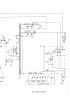
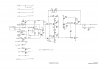
I attach the circuit diagrams for the power supply and the EHT / CRT boards. These show the transformer AC outputs and the DC rail voltages.
There were some postings some years ago about the Cossor 4100 on the UK Vintage Radio Repair Forum, which you may find helpful. www.vintage-radio.net/forum/forumdisplay.php?f=36.
The Cossor 4000 referred to recently is different. wme_bill m0wpn
The service manual is thanks for his cool part! These electric circuit diagrams are very important for me. I will measure the voltages and I check everything. Thanks for everything!
This site uses cookies to help personalise content, tailor your experience and to keep you logged in if you register.
By continuing to use this site, you are consenting to our use of cookies.