Electro Tech is an online community (with over 170,000 members) who enjoy talking about and building electronic circuits, projects and gadgets. To participate you need to register. Registration is free. Click here to register now.
Welcome to our site! Electro Tech is an online community (with over 170,000 members) who enjoy talking about and building electronic circuits, projects and gadgets. To participate you need to register. Registration is free. Click here to register now.
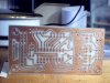
I got a bit behind the 8 ball. Excuse yes. I have 2 of the original version drilled but not etched. If you want I can etch one of them OR behind door number 2 is a new version with better spacing (easier to solder) and 8 charlieplexed LEDs. I can etch the first in a day or two but the new board is will be about a week longer. Your choice.
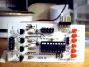
Version 2B includes bulb sensing and 6 charlie plexed LEDs for use as state indicators for debugging.
The PCB was tested with a 16F88 but it should also work with an 18F1320 or 18F1330 but the software will be a bit more difficult. The schematic indicates which signals change.
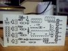
The attached schematic contains notes about the solder jumpers etc.
Thanks. It should also work as a Simon board. Use push buttons instead of switches.
Debug bits RB 6 & 7 are used by the switches. You can still debug but you have to leave these switches open. It was sort of ugly. Thus the LEDs may come in handy when doing non-debugger testing. Also I think Krumlink wants to use one of these to blink LEDs in his modded CD case.
Only a "bit" more difficult. The LEDs lines are on both PORTA and PORTB for the 18F. Not a big deal, maybe to minor to mention.
If anyone has problems opening the files try right click then open instead of clicking on the link.
One thing I noticed when playing with the box is that it works best in a formal setting where the person on the other side of the box does not feel free to grab the thing and start playing with it. You can loose control of the illusion...
When I showed it to my home school student I was using it in the timeout mode. She grabbed the box and started flicking switches. She opened the box and examined the inside for a while. The box timed out and when she resumed flipping switches it seemed broken. I responded that she had let the magic out of the box when she opened it. I did an incantation over the box, reprogrammed the switches, and handed it back to her. Now she was too old to fall for the mumbo jumbo but it was fun.
These days I am collecting the hardware for this project. I will assemble a small and a big version. For the bigger one I am looking for old fashioned black lever switches - I know they are sold in China for common 230 volt housing use ( a colleague will send a parcel to me from China). The time until arrival of that parcel will be used to built up a wooden case. With the use of some coax cables (audio cable) I will try to built up a wiring that hides the real wiring - so I try to show all the wiring in a clear perspex case. Of course it should look a little bit antique (like a glass tray) with mahagonny framing.
You are correct. This is the slight of hand I was talking about much earlier. It is an old staple. Ask a person to pick a hand then keep or discard without regard to the choice. The magician never specifies if he is going to keep or discard your choose. Because of that most people do not catch on.
This is actually a principle in magic called "Magicians Choice" and requires that the magician not ask the subject to pick a hand but rather "name" a hand or other object. That way, if the subject 'picks' the hand containing the desired object, it becomes the "one you selected" but if this is the 'wrong hand', it becomes the "one we eliminate". As was correctly pointed out, by not specifying what the magi is going to do makes the outcome completely within his/her control.
This is a great thread and while many magicians would view this as 'exposure', the magic really is in the presentation, not in the clever use of uProcessor power to make it happen.
Doug
Do you mean the code for the magic switchbox project ? Sure. I can not do it right now because I have to hunt it down and make sure it is presentable. Busy with another must get done thing.
Do you mean the code for the magic switchbox project ? Sure. I can not do it right now because I have to hunt it down and make sure it is presentable. Busy with another must get done thing.
I need to review the code prior to posting it. Between the two verison of the board I switched for a 16F to an 18F processor. The new board has never been tested with full lights and switches. I want to do that prior to publishing it.
In addition to that which is needed for the original application the V2 board has provisions for 6 charlieplex LEDs and a speaker.
Oooops I'm sorry I cannot see any video in that link.So I don't know what you guys talking about & talking about what? Can you show me where is this Video?
This site uses cookies to help personalise content, tailor your experience and to keep you logged in if you register.
By continuing to use this site, you are consenting to our use of cookies.

")