Electro Tech is an online community (with over 170,000 members) who enjoy talking about and building electronic circuits, projects and gadgets. To participate you need to register. Registration is free. Click here to register now.
Welcome to our site! Electro Tech is an online community (with over 170,000 members) who enjoy talking about and building electronic circuits, projects and gadgets. To participate you need to register. Registration is free. Click here to register now.
Standard 5% resistors have 24 values per decade (E24). I haven't used 10% resistors for about 47 years so maybe they had only 12 values per decade (E12).
Standard 5% resistors have 24 values per decade (E24). I haven't used 10% resistors for about 47 years so maybe they had only 12 values per decade (E12).
A decade is 10 times. A decade of resistance values starts the decade at 1k and goes 1.1k, 1.2k, 1.3k, 1.5k, 1.6k, 1.8k, 2k, 2.2k etc up to 9.1k. The next decade starts at 10k and goes up to 91k.
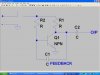
I find this circuit in my old electronics book, it is oscillator.
It is designed by sombody who knows nothing about electronics because it is not an oscillator. An oscillator has positive feedeback. This transistor does not have positive feedback, instead it has negative feedback at high frequencies.
Also the transistor is poorly biased by only one resistor from the positive supply so it is turned on all the time.
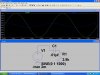
I guess the low level is the output because a highpass filter attenuates the signal. The frequency is too low at 1kHz so the attenuation is high and the phase-shift appears to be almost 90 degrees. The phase-shift will be 60 degrees and the attenuation will be less at a higher frequency.
180 degrees is half-way around.
90 degrees is a right angle.
60 degrees is 1/3rd of half way around.
Simply design a phase-shift oscillator the has three RC filters that have exactly the same R and C values. Then each RC filter produces a phase-shift of 60 degrees. It is easy if you use an amplifier with a high input impedance like a darlington transistor or two opamps.
This site uses cookies to help personalise content, tailor your experience and to keep you logged in if you register.
By continuing to use this site, you are consenting to our use of cookies.

")