koolguy
Active Member
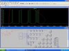
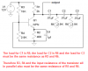
Look at this image.
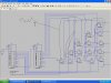
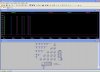
Use TOOLS/copy to clip board OR write to wmf file.
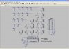
If you have Microsoft PAINT, paste the Copied clip into it.
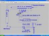
EDIT:
Download this free screen grabber,
ScreenHunter Free - Free software downloads and software reviews - CNET Download.com
Sir, This software now creating problem as when, i starts my computer it window come automatically in front why??
Pls. help..!!