Continue to Site

Welcome to our site!

Electro Tech is an online community (with over 170,000 members) who enjoy talking about and building electronic circuits, projects and gadgets. To participate you need to register. Registration is free. Click here to register now.

  • Welcome to our site! Electro Tech is an online community (with over 170,000 members) who enjoy talking about and building electronic circuits, projects and gadgets. To participate you need to register. Registration is free. Click here to register now.

LTSpice Model - Loudspeaker

Status
Not open for further replies.

eTech

Well-Known Member
Hi

Someone here expressed interest in using spice models of loudspeakers.

I've uploaded a loudspeaker library file, with symbols, and test circuit.
Instructions for adding models to the library is contained within the file.
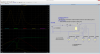
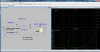
I've also uploaded a snapshot of test circuit and impedance plot.

eT
 

Attachments

  • Loudspeaker.zip
    3.3 KB · Views: 4,889
  • WooferTest.png
    WooferTest.png
    184.8 KB · Views: 5,895
The impedance curve of the woofer is interesting but the fact remains that this is due to mechanical resonance and is taken in free air. A woofer used in free air would be an interesting thing to see? The whole purpose of an enclosure is to control the cone resonance so that in real life, the impedance plot looks NOTHING like the free air plot. The purpose of the free air plot is to determine the electromagnetic damping of the loudspeaker itself. This plot is then modified by the effect of the enclosure; and the air loading of the enclosure is selected to control the Q and frequency of the resultant cone resonance. The amplifier output impedance also plays a part in the system and is used to provide the optimum electromagnetic damping of the SYSTEM.
Just not sure that spice is able to do all this.
The Thiele/Small parameters are what is needed to do the job.
Hope this helps.
 
I speaker is greatly effected by the enclosure at and near resonance. The modeling was done to match the data sheet, not the speaker in a certain box. eTech did a great job of matching the data sheet!

This project started out looking at crossovers not speakers. I objected to studding a crossover network where the speakers are '8 ohm resistors'. We were really only looking at the frequencies where the power shifts from one speaker to another. We only needed to model the inductive part of the base speaker. (only looking at the top end of its range)

I would love to see (some one not me) make models for ported boxes. That is beyond this project.

I do not want to sound like I disagree with Rumpfy. I agree with Rumpy.
 
Whilst I've not looked at the contents of the zip, the impedance plot looks perfectly reasonable for a sealed box (is this what's implied by the IB in the model name?). The impedance plot of a sealed box will have the same general shape as that in free air, since the compliance of the box volume simply modifies the compliance of the driver suspension. Put another way, a sealed box is a system with only one reactive component and so can't contribute a resonance of its own.

It's certainly possible to model any kind of speaker cabinet as an electrical circuit in spice - you just have to translate your acoustic units into electrical ones, or your electrical units into acoustical ones, depending upon which is more convenient. It's a bit disorientating, but certainly a good way of doing a first-order simulation of the behavior of a speaker system. Obviously you can plug in your amplifier impedance, cabling and crossover too if needed.
The big stumbling block is quantifying the damping (resistance) in the acoustical system - while there are good theoretical and empirical formulae for calculating compliance and mass (capacitance and inductance) from the mechanical dimensions of the cabinet, the same is not true of damping (not to my knowledge, anyhow). This leads to some guesswork regarding the Q of the system...

If I remember I'll dig out some of my notes from university and post them in case they are useful.
 
A sealed enclosure simply prevents out-of-phase low frequencies from the rear of the speaker from cancelling sound from the front of the speaker. Because the air in the box is an additional spring against the cone then the volume of the enclosure raises the resonant frequency of the speaker. If the enclosure is filled with a sound absorbing insulation like fiberglass then the effective size of the enclosure is increased resulting in the resonant frequency being reduced a little because the sound waves in the insulation are converted to heat waves.

The sealed enclosure provides full output at resonance then reduced sound level at -12dB per octave below the peak.

A ported enclosure can produce full output at lower frequencies then reduced sound level at -24db per octave below the peak. Then it might produce less deep bass than a sealed enclosure.
 
What audioguru says is true... the port adds an extra reactive element (a mass or inductance type reactance), giving the cabinet a distinct resonance of its own. Cascaded with the resonance of the driver, this results in the steeper roll-off below resonance.

I've dug out that piece of university work and had a brief look over it (for the first time in years). Bear in mind that it's an assignment rather than a tutorial, but I think it gives a pretty good walk-through of how to derive an electrical speaker model. Note that in this treatment I think everything ends up in acoustical units - you might need to start from "the other end" of the circuit and change everything into electrical units. Also we ignore the voice coil impedance - you may want to leave this in if you're interested in modeling crossovers.

This kind of analysis is called a "lumped parameter" model (at least, that's what we called it). You can model any kind of cabinet by simply changing the rear load of the driver (and the front load too, for a bandpass box!).

Hope this is useful.
 

Attachments

  • Bass Reflex.pdf
    817.7 KB · Views: 2,503
Erratum... I've just spotted that on page 4 the denominator of the first equation should be Sv^2 (like it says in the text) not just Sv.
Tut tut...
 
The impedance curve of the woofer is interesting but the fact remains that this is due to mechanical resonance and is taken in free air. A woofer used in free air would be an interesting thing to see? The whole purpose of an enclosure is to control the cone resonance so that in real life, the impedance plot looks NOTHING like the free air plot. The purpose of the free air plot is to determine the electromagnetic damping of the loudspeaker itself. This plot is then modified by the effect of the enclosure; and the air loading of the enclosure is selected to control the Q and frequency of the resultant cone resonance. The amplifier output impedance also plays a part in the system and is used to provide the optimum electromagnetic damping of the SYSTEM.
Just not sure that spice is able to do all this.
The Thiele/Small parameters are what is needed to do the job.
Hope this helps.

Hi

I didn't state it in the Library file anywhere, but the parameters used for each of the models are Thiele/Small parameters taken from the data sheets. To add a new model, just plug in the parameters. And no, I didn't provide any enclosure modeling but have seen numerous papers on spice simulations for that as well.

eT
 
Last edited:
What audioguru says is true... the port adds an extra reactive element (a mass or inductance type reactance), giving the cabinet a distinct resonance of its own. Cascaded with the resonance of the driver, this results in the steeper roll-off below resonance.

I've dug out that piece of university work and had a brief look over it (for the first time in years). Bear in mind that it's an assignment rather than a tutorial, but I think it gives a pretty good walk-through of how to derive an electrical speaker model. Note that in this treatment I think everything ends up in acoustical units - you might need to start from "the other end" of the circuit and change everything into electrical units. Also we ignore the voice coil impedance - you may want to leave this in if you're interested in modeling crossovers.

This kind of analysis is called a "lumped parameter" model (at least, that's what we called it). You can model any kind of cabinet by simply changing the rear load of the driver (and the front load too, for a bandpass box!).

Hope this is useful.

Hi:)

Wow...except for the coupled inductors and the acoustic section, the topology looks very similar to the model I used.
Maybe I'll try retrofitting an acoustic section as a future project. ;)
Useful info....

eT
 
Thieles original; paper was complete. It started with the system looking like a Butterworth filter but then extended the analysis to several 'alignments'. The interesting bit is the extension to Chebychev alignments where there is allowed to be passband ripple. The Cas/Cab ratio of 1.4 sets the limit between Butterworth and Chebychev. All this need to be considered in the frequency response/efficiency analysis. In terms of fidelity, there were a series of listening tests done in the 1960's at the Australian Broadcasting Commission, and the conclusion at that time was that the RCA LC1/LC1A speakers designed by Harry Olsen in the 1940's were the most accurate sound reproducing speakers around. Who can afford such items today?
 
...........................................

The sealed enclosure provides full output at resonance then reduced sound level at -12dB per octave below the peak.

A ported enclosure can produce full output at lower frequencies then reduced sound level at -24db per octave below the peak. Then it might produce less deep bass than a sealed enclosure.
I know that being ported or not seems to have a significant affect on the woofer transient response (at least in my limited experience). I bought an inexpensive (read cheap) Sony 10" ported powered subwoofer to augment the bass in my home-kludge system for my computer (50 year old Dynakit Stereo 120 basic amp and 25 year old JBL bookshelf speakers). The bass was rather muddy and one-note (I suppose due to the port resonance) so I tried plugging up the port with an old sock. That greatly improved the bass, being tighter sounding, and making it much easier to actually tell the difference in the various bass frequencies. Plugging the port may have reduced the maximum bass output but the improvement in bass fidelity was well worth it, and the bass volume is still more than adequate.
 
A sub-woofer is not supposed to sound like "Bose one-note-bass from a small speaker". It should not have a peak that sounds resonant but it should have a flat frequency response until it naturally rolls off.
A ported enclosure should have a fairly good transient response with its slow rise-time and slow fall-time not obvious.
 
Hi
Here's a version with Acoustics modeled as well..

eT :)
 

Attachments

  • WooferWithPortedBox.png
    WooferWithPortedBox.png
    489.5 KB · Views: 1,745
I think you have a BOOM box that has a +6dB peak at about 28Hz probably caused by the 10 ohm resistor in series with the speaker. The extremely low output impedance of a modern amplifier damps resonances like that so the speaker response should be completely flat.

Here is the response of a little woofer in a vented enclosure:
 

Attachments

  • Vifa XT18WH  6.5inch woofer in vented enclosure.png
    Vifa XT18WH 6.5inch woofer in vented enclosure.png
    311.5 KB · Views: 1,284
Status
Not open for further replies.

Latest threads

New Articles From Microcontroller Tips

Back
Top