Continue to Site

Welcome to our site!

Electro Tech is an online community (with over 170,000 members) who enjoy talking about and building electronic circuits, projects and gadgets. To participate you need to register. Registration is free. Click here to register now.

  • Welcome to our site! Electro Tech is an online community (with over 170,000 members) who enjoy talking about and building electronic circuits, projects and gadgets. To participate you need to register. Registration is free. Click here to register now.

LTspice help

Status
Not open for further replies.

XL-power

New Member
hi all,,
again my problem with LTspice
i was asking in this topic https://www.electro-tech-online.com/threads/ltspice.109453/
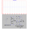
how can i draw power versus different resistors and people there gave me the solution and i do it and yes i get power versus resistor
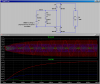
but the problem is that the dissipated power is zero. i solve the problem numerically but the power is not equal to zero

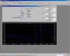
this is what i did, any help please?
 

Attachments

  • equivalentcircuit.png
    equivalentcircuit.png
    54.9 KB · Views: 365
Several observations:

Before you worry about stepping the load resistance, the basic circuit has to make sense and simulate.

1. The network R1, L1, C1 and C2 are driven by an ideal voltage source, so cannot have an effect upon the voltage at the input of the full-wave bridge rectifier. If you are attempting to model some sort of resonance, you should use a current source (infinite output impedance) to excite that network, or reconfigure the network so it is not in parallel with a voltage source.

2. With the voltage at the input of the full-wave bridge of only 1.44V p-p, the forward voltage drop of the Silicon diodes (the default diode) will just barely conduct, so I'm not understanding what you are trying to do?

Being curious, I reconnected the voltage source in series with C2, and then swept the frequency around your stimulus frequency of 230Hz. Note that the series resonance of this network is close to 230Hz. The parallel resonance is close to 248Hz.

However, if this connection mimics what you are trying to do, note that the amplitude out of the network at the series resonance is so small, you would get nothing out of the full-wave bridge even if it was hooked up...
 

Attachments

  • DF1-1.png
    DF1-1.png
    66.4 KB · Views: 390
  • Draft1-1.asc
    718 bytes · Views: 303
Last edited:
Several observations:

Before you worry about stepping the load resistance, the basic circuit has to make sense and simulate.

1. The network R1, L1, C1 and C2 are driven by an ideal voltage source, so cannot have an effect upon the voltage at the input of the full-wave bridge rectifier. If you are attempting to model some sort of resonance, you should use a current source (infinite output impedance) to excite that network, or reconfigure the network so it is not in parallel with a voltage source.

2. With the voltage at the input of the full-wave bridge of only 1.44V p-p, the forward voltage drop of the Silicon diodes (the default diode) will just barely conduct, so I'm not understanding what you are trying to do?

Being curious, I reconnected the voltage source in series with C2, and then swept the frequency around your stimulus frequency of 230Hz. Note that the series resonance of this network is close to 230Hz. The parallel resonance is close to 248Hz.

However, if this connection mimics what you are trying to do, note that the amplitude out of the network at the series resonance is so small, you would get nothing out of the full-wave bridge even if it was hooked up...

1- i rewrite the input voltage source in terms of L1,C1,C2 and R
2-am trying to convert the AC output voltage from the piezo circuit to DC,,, so what is the wrong with diodes?
 
The forward drop across Silicon diodes (~0.65V) is so high compared to the output of your simulated piezo at 230Hz, that there will be no output.

Here is the time-domain output at 230Hz (Green), 240Hz (Blue), and 250Hz (Red). Note that to show the voltage across R2, I had to plot the expression V(a)-V(b).
 

Attachments

  • DF1-2.png
    DF1-2.png
    50.9 KB · Views: 343
  • Draft1-2.asc
    1.9 KB · Views: 318
The forward drop across Silicon diodes (~0.65V) is so high compared to the output of your simulated piezo at 230Hz, that there will be no output.

Here is the time-domain output at 230Hz (Green), 240Hz (Blue), and 250Hz (Red). Note that to show the voltage across R2, I had to plot the expression V(a)-V(b).

thanks a lot "Mike ML",, all the best for you

so if i change the diode so the ripple voltage can be ignore, will i get an output?
 
What voltage do you expect to get at the input to the full-wave-bridge?
 
Status
Not open for further replies.

Latest threads

New Articles From Microcontroller Tips

Back
Top