normad
Member
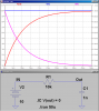
I started using Ltspice because most of the users here recommendded it.. now im trying to view the transient curve of a voltage of a capacitor when a dc voltage is applied..
for this i used a voltage source with a pulse of 5 volts and a 10 k resistor in series with a 1n capacitor.. but in the process of charging the capacitor the curve is a line instead of the exponential curve which is given by the equation. please help. im trying to understand dc transients using this..
thanks in advance
")