ahmedragia21
Member
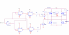
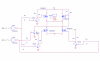
Hi, i tried to design many h-bridges and i found many faults in them and im in the need of a working one using MOSFETS not BJTs , the problem is its too hard to drive the MOSFETs correctly ... do someone has a working one cuz i want to send it to the pcb company and made it ... ? i googled i found some circuits but they cants stand more than 5A, and also im not sure whether they can work or not...
Thanks !
Thanks !
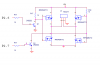
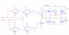
") so please tell me if it can work or has a probability of not working?
so please tell me if it can work or has a probability of not working?