Electro Tech is an online community (with over 170,000 members) who enjoy talking about and building electronic circuits, projects and gadgets. To participate you need to register. Registration is free. Click here to register now.
Welcome to our site! Electro Tech is an online community (with over 170,000 members) who enjoy talking about and building electronic circuits, projects and gadgets. To participate you need to register. Registration is free. Click here to register now.
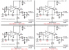
That LTS opa is based on a CA3140 and has been set for rail to rail.
If you look at the CA3140 you will see that it has inputs that work to -.5v below 0V.
EDIT:
I have tried a number of singles and double rail/rail opa's, I still get a similar response, I would be pleased to see what you get with LTS.
The stock CA3140 opamp should work perfectly in my peak detector circuit without any modifications except it is extremely noisy.
I don't know why its gain is wrong.
I will build this one with MC33171 today afternoon and let you know how it went. Could I get some details before that how to adjust the gain in this circuit, I think I'll just change the resistor there until I get good response with my mp3 player.
I also had plans to use two led in series per output to reduce the load on the chip, but when I tried it, the other LED stayed unlit. the ones going straight to the positive rail lit like previously, but the new ones between the chip and the old LEDs didn't lit at all. I had the LEDs correctly: chip pin > LED1- > LED1+ > LED2- > LED2+ > positive rail
hi,
I would be interested in the results of your MC33171 experiment, sometimes simulators give unexpected results.
Reference the LED's, If I recall they are Blue or White, 2 of those colours in series should work ok, providing you are still using +12V.?
So its LED1 anode to +12V, LED1 cathode to LED2 Anode and LED2 cathode to the LM3915 pins..OK
Yes, I'm still using +12V. I'm sure I have the LEDs in correct way, I really just added the LED #2 between the chip and the old LED #1 in the breadboard. But still, the LED #2's won't light together with the LED #1's. The LEDs are all OK condition, I tested them separately before and after these tests.
Yes, I'm still using +12V. I'm sure I have the LEDs in correct way, I really just added the LED #2 between the chip and the old LED #1 in the breadboard. But still, the LED #2's won't light together with the LED #1's. The LEDs are all OK condition, I tested them separately before and after these tests.
hi,
I would suggest that you do a quick test: connect two LED's in series with a series resistor, say about a 470R, across +12V and 0V,,check that they do light when not connected to the LM3915
Could I get some details before that how to adjust the gain in this circuit, I think I'll just change the resistor there until I get good response with my mp3 player.
When the source has a low impedance, the gain of the inverting opamp is simply the ratio of R8/R9. Since the input coupling capacitor C4 is in series with R9 then the low cutoff frequency is determined by "one over two pi RC" as shown here:
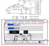
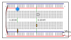
Ok, I built one. When I power it up, every LED stays unlit. In the picture is the illustration of how I did it.
3915 pins are showing what they should be showing, all the ground pins 0V, +12V pins 12.3V, pins #6&7 1.25V and pin #5 0V.
I tried to input some audio from the mp3 player, but nothing happens, voltage on pin #5 and on the 2N3904 stays 0V. I checked with multimeter if any AC is coming from the player, the connections work, audio signal is going to the board.
EDIT: Could it be that the MC33171 pins are wrong in the picture?
Yes.
You copied my "preamp and peak detector" circuit from post #89. It clearly shows an MC33172 8-pins dual opamp.
When using an MC33171 single opamp then you must use its different pins.
Breadboards are a tangled nightmare of crossed and diagonal wires and parts. I use stripboard where the layout is neat and tidy and parts are soldered so nothing is intermittent.
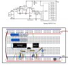
I had to substitute the 100R resistor with nearest counterpart I had(1k) for now, but it works nevertheless. Now I can move on to the casing and getting the signal divided from mp3 player to both amplifier and the VU meter circuit. Oh, and getting the second row of LEDs to work too...
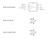
I think my LED problem is related to breadboard again. There's something odd about how it works or I'm not doing something right. I've made a picture of two setups with LEDs, A and B.
A works like it should, LED lits up.
B doesn't work, LED stays unlit. In addition, if I remove the last jumper wire going from resistor to the ground, LED flashes briefly and burns up.
What I'm not seeing here? EDIT: PLENTY. SHORT CIRCUITS GALORE.
This site uses cookies to help personalise content, tailor your experience and to keep you logged in if you register.
By continuing to use this site, you are consenting to our use of cookies.

")