Continue to Site

Welcome to our site!

Electro Tech is an online community (with over 170,000 members) who enjoy talking about and building electronic circuits, projects and gadgets. To participate you need to register. Registration is free. Click here to register now.

  • Welcome to our site! Electro Tech is an online community (with over 170,000 members) who enjoy talking about and building electronic circuits, projects and gadgets. To participate you need to register. Registration is free. Click here to register now.

LM3915 LED VU meter problem - pictures included

Status
Not open for further replies.

Gaichuke

New Member
Hello,

I built yesterday LM3915 based LED VU meter, but it doesn't work. Not a single LED light up.

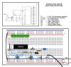
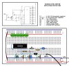
Since I'm a complete beginner with electronics (I learned what a diode is yesterday) there's a fair chance I've done some elementary mistake somewhere. I'll uploaded a picture showing the circuit, part list and an illustration of my breadboard with all the parts in it as they are.

If it's not a too much bother, please look the pic and tell me what's wrong with my assembly. Also if you have patience, tell me why it's wrong, so I could learn something as well.

Thank you in advance!
 

Attachments

  • BB_copy..jpg
    BB_copy..jpg
    191.9 KB · Views: 6,007
Last edited:
It looks like the transistor is backwards.

Pins 10 through 18 are the reverse of what you show. But that shouldn't prevent the circuit from working.
 
According to the schematic, you must input positive pulses at least 11.4 volts high for the transistor to shut off and let C2 accumulate a charge...which leaks off at a rate of about 10 Hz. It looks to me like you're not making a VU meter. You're counting positive pulses greater than 11.4 volts. Is this your intent?
 
mneary: I'll check the transistor, thanks for the tip.

bychon: My intent is to have a VU meter for audio signal, I copied the schematic from here:

Sound Level Meter

I didn't understand anything else you said, but the schematic should work as it is.
 
It looks like you copied the schematic correctly. I'll have to ponder why I don't understand the input transistor.
 
One thing is transistor connected backwards(as already mentioned). Also it won't light up any LED's if the input signal level is too low. Also you could add a pot at the input for setting up the level of response(like a volume control).
 
Last edited:
One thing is transistor connected backwards(as already mentioned). Also it won't light up any LED's if the input signal level is too low. Also you could add a pot at the input for setting up the level of response(like a volume control).

That's a very good point. I think that the original schematic mentions that "The input is designed for standard audio line voltage (1V P-P) and has a maximum input voltage of 1.3V.".
I will be using a mp3 player input, I think those have much lower input voltage than 1V.

How should I then change this design for mp3 player input? I think pot would be redundant because I doubt this will ever have anything else than mp3 player audio input.

hi,
The front end amplifier works ok, the transistor is not drawn the wrong around.

Look at this quick LTS sim of the amp.


lm3915..gif
 
Last edited:
hi,
Look at this image which shows a LM3914 using your circuit values, the LED display is linear not logarithmic as the LM3915, but it shows it working.
As each LED is about 15mA and the supply is 12V, in Bar mode, you should have a 22R in the 12V to the LEDs linked Anodes.

AAesp06..gif
 
Last edited:
That's a very good point. I think that the original schematic mentions that "The input is designed for standard audio line voltage (1V P-P) and has a maximum input voltage of 1.3V.".
I will be using a mp3 player input, I think those have much lower input voltage than 1V.

How should I then change this design for mp3 player input? I think pot would be redundant because I doubt this will ever have anything else than mp3 player audio input.

hi,
You can make the LM3915 more sensitive to lower signal levels.

Disconnect Pin #6.
Connect a 5K pot from pin #7 to 0V.
Connect the wiper of the pot to pin #6.

By adjusting the pot you can set the LM3915 to display mVolt audio signals.

Do you follow OK.?
 
Hi eric,
The peak detector transistor seems to be connected wrong way around in breadboard :)

hi,
That breadboard layout does show the 2N3906 reversed, I did say the transistor is not drawn the wrong way around.

OP, can you confirm that the 2N3906 is inserted in the board as you show on that layout.?
 
It looks like you copied the schematic correctly. I'll have to ponder why I don't understand the input transistor.

hi bychon,
This explains the function of the PNP transistor.
AAesp07..gif
 
Ok, I did a revision to my setup based on the comments here.

ericgibbs: Yes, the transistor is inserted in the board as in the layout. I've reversed it in the revised one. I also did the changes you mentioned with the 5K pot. I hope I did it correctly. I presume the original R1 is not needed anymore with this configuration, and I removed it.

Here's the new pic:
 

Attachments

  • BB_copy_revised..jpg
    BB_copy_revised..jpg
    193.5 KB · Views: 763
Ok, I did a revision to my setup based on the comments here.

ericgibbs: Yes, the transistor is inserted in the board as in the layout. I've reversed it in the revised one. I also did the changes you mentioned with the 5K pot. I hope I did it correctly. I presume the original R1 is not needed anymore with this configuration, and I removed it.

Here's the new pic:

hi,
R1 is needed, put it back in place.:)

EDIT: it should be between pins 7 and 8
 
Last edited:
R1 between pins 7 and 8, ok.

What about that pot setup, was that one OK?

hi,
Connect your audio source, mp3 input to the input capacitor, turn up the volume and then adjust the 5K pot.
You should see some of the LED's light.

If NOT let me know.:)
 
Last edited:
Status
Not open for further replies.

New Articles From Microcontroller Tips

Back
Top