Nice .. so as i have made this one circuit working with Lm7806 i can supply with some voltage the lm3914...
as i saw from your lovely executable program for lm3914... 6v or 8v dont make any difference in the operation...
right?
10μf ? you are talking about the slosh filter schematic ? only there is these capacitors ...
1μ = 1μf = 1 micro farad ? ( i went to the electronic shop today and he stacked with that.. couldnt remember if it is right )
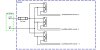
Question : in case we are not using the second opa in lm358 do we have to ground the ''non inverting input'' .
And bridge the op2 ''inverting input'' with the opa2 ''output'' ??
i read it somewhere in the net about this... and i am not sure what this will make better to the circuit
as i saw from your lovely executable program for lm3914... 6v or 8v dont make any difference in the operation...
right?
10μf ? you are talking about the slosh filter schematic ? only there is these capacitors ...
1μ = 1μf = 1 micro farad ? ( i went to the electronic shop today and he stacked with that.. couldnt remember if it is right )
Question : in case we are not using the second opa in lm358 do we have to ground the ''non inverting input'' .
And bridge the op2 ''inverting input'' with the opa2 ''output'' ??
i read it somewhere in the net about this... and i am not sure what this will make better to the circuit
Last edited:

") )
)