Continue to Site

Welcome to our site!

Electro Tech is an online community (with over 170,000 members) who enjoy talking about and building electronic circuits, projects and gadgets. To participate you need to register. Registration is free. Click here to register now.

  • Welcome to our site! Electro Tech is an online community (with over 170,000 members) who enjoy talking about and building electronic circuits, projects and gadgets. To participate you need to register. Registration is free. Click here to register now.

LM386 Stereo Headphone Amp - Dual Output Possible?

Status
Not open for further replies.

TheNewGuy

Member
Hey Everyone,
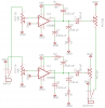
So I'm gathering parts for this Stereo Headphone Amplifier I'm putting together powered by two LM386 IC's when I got this idea: would it be possible to have more than one auxiliary output jacks? Below is my refined schematic with bass boost that I got off of the LM386N-1 Datasheet.

The reason I would want to do this is because I have stray stereo speakers that use auxiliary jacks that do not have amplifying circuits of their own, so my reasoning is having more than one auxiliary output jacks so I could have two speakers instead of just one...would it be reasonable to do?

-TheNewGuy

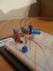
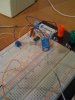
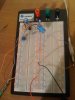
PS- I am thinking of going and getting a copper PC board and some etchant for the final product after I breadboard it out.
 

Attachments

  • LM386 Headphone Stereo Amplifier.png
    LM386 Headphone Stereo Amplifier.png
    19.2 KB · Views: 12,937
Last edited:
It looks like a complete crap circuit to me especially with a pot at the output of LM386. I won't recommend a dual output as one for headphone and other for non-amplified stereo speakers!

Instead, use either a TDA7050 or 2822M(ST Micro) specially made for headphone stereo operation, no worries.

Also you can make a separate TDA2822M for your stereo speakers. I've a desktop computer speaker that uses this IC, low power but doing a well job as a basic stereo power amplifier.
 
Your 9V battery needs a 470uf capacitor across it on the pcb.
A 9V battery will not last long. Six AA cells will last 5 times as long as a 9V battery.
With bass boost then the average power at higher frequencies is only 0.113W per channel when the 9V battery is brand new when the boosted bass frequencies are clipping.
 
It looks like a complete crap circuit to me especially with a pot at the output of LM386. I won't recommend a dual output as one for headphone and other for non-amplified stereo speakers!

Instead, use either a TDA7050 or 2822M(ST Micro) specially made for headphone stereo operation, no worries.

Also you can make a separate TDA2822M for your stereo speakers. I've a desktop computer speaker that uses this IC, low power but doing a well job as a basic stereo power amplifier.

Complete crap...oh well...I'm open to advice and I want to learn. Thanks for the IC suggestions, I might use them...

Your 9V battery needs a 470uf capacitor across it on the pcb.
A 9V battery will not last long. Six AA cells will last 5 times as long as a 9V battery.
With bass boost then the average power at higher frequencies is only 0.113W per channel when the 9V battery is brand new when the boosted bass frequencies are clipping.

I'm going to ditch the rest of the stuff and just have two normal LM386's so I can run it off of a 9V battery and it'll drive headphones. This will just be my first test and project...later I'll use the IC's transistor495 suggested for something more serious.

The confusing part for me is that I make a list of parts I need but after more reaserching I find another variation of the same circuit. There are so many different ways of doing it I don't know what circuit I should use. I also don't know the in's and out's of a circuit to correct problems that I see in a circuit...like the capacitor after the 9V connection.
 
a TDA2822M amplifier is too powerfull for headphones, even a regular 386 might be too big. but keeping in mind what audioguru said, you can add a voltage regulator to prolong the performance life of your amp, during the useful life of your battery.
 
The voltage from the cigarette lighter plug of a car is the 12V battery when the alternator is not charging up to 14.4V when the engine is running fast. The current is as much as the load draws up to where the fuse blows.

On every datasheet of every voltage regulator IC there is the "dropout voltage". Guess what it is? It is the minimum amount of extra input voltage where the regulator is not regulating.
The 7809 amd L7809 have a minimum input voltage of typically 11V but could be as high as 11.5V where the IC is not regulating because its input voltage is too low.
 
a TDA2822M amplifier is too powerfull for headphones,

There shouldn't be any problem at a 3v supply. I haven't made a 2822M till now:), but I can say it'll be a good performer as a headphone amp...and it is used in cheap desktop computer speakers(I have one) with a highly rated output(very low power for the job, not recommended)..I own around ten 2822M of ST microelectronics. Cheap chinese copies are available everywhere.
 
true, but you didn't bring up your supply voltage. i am working on a TDA2822M bridge amplifier circuit for my iPod. what you have too appreciate about the circuit is the extreemly ghetto housing it's in (aka a card board box)
 
An LM386 is fine for a headphone amplifier.

There's no need connect any potentiometers to the output; there only needs to be a volume control on the input.

The power supply voltage doesn't need to be regulated so there's no need for an LM7809.

The LM386N-4 is fine all the way up to 18V and can run off a car battery with out a regulator. All that's needed is a 15V zener diode and a 10R series resistor to protect it against voltage transients.

The LM386N-1, -3 has a supply voltage range of 4V to 12V and will last for a long time connected to a little 9V battery powering 32Ω headphones. I would recommend using four AA cells which will probably last longer, although I've not done the calculations so I could be wrong.
 
Last edited:
I bought a breadboard and I built the circuit that had 1 LM386 and two LM386's, and the bass boost circuit in the datasheet, no matter what I did the quality of the sound was horrible! But I can upload pictures of it if you guys want (my first circuit on a breadboard)?

I was so exited though to hear sound even though it was crappy. :)

EDIT: Any ideas to decrease distortion?
 
Last edited:
One idea is to use better amp chip:eek:
You need to say more about the input signal you're feeding it up. Are you able to adjust the volume using the put pot?, else re-wire it. Please don't test your amp while listening through headphones!

Post good quality double sided pictures.
 
An LM386 amplifier has good response up to 500kHz so it will probably oscillate when built on a breadboard. The bass boost circuit adds extra negative feedback at high frequencies which increases the possibility of oscillation.

Make it on a compact pcb or stripboard and use a proper supply bypass capacitor that is not shown in the datasheet.

The distortion is typically only 0.2% with an 8 ohm load and is much less with 32 ohm headphones.
 
Wow!
I built **broken link removed** schematic looking for a circuit for the LM386 that had less oscillation, and this one is SO much better! And I'm only using one LM386 right now.

EDIT: I was also looking through my stash of Electrical Components and found a 35V 1,000uF capacitor that I forgot I had. :p
 
Last edited:
I bet once it is on a PCB it would sound even better like AudioGuru said. :D

EDIT: So you guys know, the input is an MP3 player and the output is a stereo speaker through an auxilary jack. I'll upload pictures.
 
Last edited:
Did you notice that the new circuit hs two supply bypass capacitors and your first circuit had none?
 
(Hits hand on face in embarrassment): Which happened to be what you were telling me from the start...

Why does the supply bypass capacitor make such a difference?
 

Attachments

  • Amp 002.jpg
    Amp 002.jpg
    523 KB · Views: 580
  • Amp 004.jpg
    Amp 004.jpg
    513 KB · Views: 518
  • Amp 003.jpg
    Amp 003.jpg
    595.3 KB · Views: 492
  • Amp 001.jpg
    Amp 001.jpg
    419.9 KB · Views: 498
Last edited:
Why does the supply bypass capacitor make such a difference?

Because the battery has a fairly high internal resistance. Then when the output draws current from the battery, the resistance of the battery causes its voltage to drop. So the battery voltage fluctuates up and down with the signal and feeds back into the input causing oscillation.
 
Status
Not open for further replies.

Latest threads

New Articles From Microcontroller Tips

Back
Top