Continue to Site

Welcome to our site!

Electro Tech is an online community (with over 170,000 members) who enjoy talking about and building electronic circuits, projects and gadgets. To participate you need to register. Registration is free. Click here to register now.

  • Welcome to our site! Electro Tech is an online community (with over 170,000 members) who enjoy talking about and building electronic circuits, projects and gadgets. To participate you need to register. Registration is free. Click here to register now.

LM317 Nicad Charging circuit - LED indicator add on ?

Status
Not open for further replies.

garycollier

New Member
Hi folks I wonder if anyone could help me out with a circuit ?
:roll:
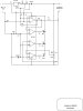
I have designed a simple slow NICAD charging circuit using the LM317 to charge a 5 cell NICAD battery pack at 9volts 700mA. For a Kirby caving lamp.

Instead of using a moving coil ammeter to monitor charge I would like to use a variable colour LED to monitor charging. With it changing from Red to Green as the battery charges.
I have looked around the web but to no avail yet. Does anyone have any ideas, advice or links ?

My electronics is a bit rusty.......

Thanks in advance,
 
Nicad charger with a LM317

From your post I am not sure what current you are charging the Nicads at.
I would assume you have the LM317 set up as a constant current charger.
If that is the case it is fairly easy to add a LED to monitor that the batteries are charging, provided your DC voltage source will add about
2 to 3 volts. By using a comparator you can detect when the batteries are
fully charged, as nicads have a individual cell voltage of very near to 1.5 volts per cell at room temperature when fully charged.

Several years ago I build a number of nicad chargers that had 3 LED's,
1 indicated applied power, 1 indicated that the batteries were charging,
and the last one illuminated when the battery pack was charged. It is a pretty straight forward circuit I would be glad to share with you if you
are interested.
 
Re: Nicad charger with a LM317

k7elp60 said:
From your post I am not sure what current you are charging the Nicads at.
I would assume you have the LM317 set up as a constant current charger.
If that is the case it is fairly easy to add a LED to monitor that the batteries are charging, provided your DC voltage source will add about
2 to 3 volts. By using a comparator you can detect when the batteries are
fully charged, as nicads have a individual cell voltage of very near to 1.5 volts per cell at room temperature when fully charged.

Several years ago I build a number of nicad chargers that had 3 LED's,
1 indicated applied power, 1 indicated that the batteries were charging,
and the last one illuminated when the battery pack was charged. It is a pretty straight forward circuit I would be glad to share with you if you
are interested.

It seems like this method could be tricky...

I thought a property of batteries NiCd's in particular was that when near full charge, the voltage changes very little. I mean the difference between say 95% charged and 99% is not that much. Now when they are almost fully discharged, that's a different matter. The voltage will drop drastically below around say the 2% level...

A comparator does not need to sense much change in voltage at all to trip but its reference input would need to be calibrated so-to-speak at very near the 100% level and how could one do that?

I've read that one of the more reliable ways of sensing 100% charge is to measure temperature of the cell. Given a constant charging current, when the cell reaches full charge, power from the cc generator must be dissipated as heat and the cell temp will begin to rise significantly, if one can sense this, then they can place the charger in a trickle state and of course, give an indication of full charge via LED or whatever..

I myself have never designed a charger so I can't speak from experience.
I'm interested to know how you accomplished 100% charge sensing without overcharge by measuring cell volts..
 
Charge Indicator Circuit

I think I know of a circuit that may be very similar to the one you used. Is it based on a comparator circuit and 4 PNP transistors ?

**broken link removed**

The cells are contained in a caving lamp battery pack so sensing the temperature would not be easy to do really. I will provide a link to the page showing the lamp and also one for the charger.

The lamp is the 2nd kit down known as the Kirby Kidney lamp:
**broken link removed**

The charger is the 2nd kit down also. I think the kit uses the LM317 with just a moving coil as an indicator:
**broken link removed**

Maybe I should consider using the PNP transistor circuit rather than the LM317 ? Maybe I could try and incorporate a comparator into the LM317 circuit..... hmmm So many options......
 
Re: Charge Indicator Circuit

garycollier said:
I think I know of a circuit that may be very similar to the one you used. Is it based on a comparator circuit and 4 PNP transistors ?

**broken link removed**

The design shown from this URL illustrates my point about the sensitivity of peak charge detection. The peak detect circuit used is clever.

In your design, I think you will want to provide the same kind of functionality as this one does.
 
Last edited by a moderator:
nicad charging

Nicad batteries have some interesting properties. The voltage on the cell
terminals
during the charge process can reach almost 1.5 volts. If the cell voltage is at
cutoff (1.0 volts) when the charger is applied the voltage will increase as the cell
charges. Let's assume the charge current is 0.1C and the temperature is 20
degrees C. When the cell is fully charged two other things happen, on the cell
temperature reaches a peak and the internal cell pressure also reaches a peak. The
interesting thing is that the cell voltage peaks a little before the other two peaks,
in fact the cell voltage peaks before full charge and the dips a little at full charge
and this dip occurs at the peak of the temperature and pressure.

I worked for over 10 years at a electronic distributor that in the value added
department, rebuilt nicad battery packs. I worked in that department for a while
and learned from the supervisor that if one is to charge a nicad battery at
.095C (capacity of the cell in Ma X.095) the cell will never over charge at room
temperature. I also learned that quality packs had an internal thermostat the
had a set of normally closed contacts. When the internal temperature reached
the temperature of the thermostat the contacts opened and current would neither
flow into the pack or out of the pack.
The attacked schematic is for a charger that was specific for a 7.2V 170MA pack, but can be modified for other batteries

The supplied schematic is a design for a 7.2V 170Ma nicad battery. By changing the values of R8(75
ohms)and R2(22ohms)it will work with other Ma capacity batteries. By changing the value of R3(560k)
the circuit will also work for other voltages. The circuit as shown will have very close to 9V at the
output terminals when the 7.2 volt battery is fully charged. This is assuming a 1.5 volt per cell for a
6 cell (7.2 Volt) nicad battery. At this condition the voltage on the high side of the 100k pot. is 0.8V.
Voltage drops for other components are typically:
R8 1.25V
R1 0.375V
D1 0.5V
LM317 2.0V
For the circuit to operate correctly the input voltage should be a minimum of 5.0 Volts higher than
the full charge voltage of the battery.
All resistors excepty R1 and R8 are 1/4 watt. The wattage of R1 and R8 depends on the charge current.
The LM317LZ will handle charge currents of to 100Ma, for higher charge currents us a LM317T.

The green LED is on when power is applied, the red LED is on when the battery is charging, and the
yellow LED comes on when the battery is charged, or if the charger is connected to power and no
battery is connected.

My recommendation is that you choose a charge current less than capacity/10. If you will give me the
charge current I will recalculate the values for R1,R8 and R3.
 

Attachments

  • NICAD_CHARGER.JPG
    NICAD_CHARGER.JPG
    29 KB · Views: 3,233
Nicad batteries have some interesting properties. The voltage on the cell
terminals
during the charge process can reach almost 1.5 volts. If the cell voltage is at
cutoff (1.0 volts) when the charger is applied the voltage will increase as the cell
charges. Let's assume the charge current is 0.1C and the temperature is 20
degrees C. When the cell is fully charged two other things happen, on the cell
temperature reaches a peak and the internal cell pressure also reaches a peak. The
interesting thing is that the cell voltage peaks a little before the other two peaks,
in fact the cell voltage peaks before full charge and the dips a little at full charge
and this dip occurs at the peak of the temperature and pressure.

I worked for over 10 years at a electronic distributor that in the value added
department, rebuilt nicad battery packs. I worked in that department for a while
and learned from the supervisor that if one is to charge a nicad battery at
.095C (capacity of the cell in Ma X.095) the cell will never over charge at room
temperature. I also learned that quality packs had an internal thermostat the
had a set of normally closed contacts. When the internal temperature reached
the temperature of the thermostat the contacts opened and current would neither
flow into the pack or out of the pack.
The attacked schematic is for a charger that was specific for a 7.2V 170MA pack, but can be modified for other batteries

The supplied schematic is a design for a 7.2V 170Ma nicad battery. By changing the values of R8(75
ohms)and R2(22ohms)it will work with other Ma capacity batteries. By changing the value of R3(560k)
the circuit will also work for other voltages. The circuit as shown will have very close to 9V at the
output terminals when the 7.2 volt battery is fully charged. This is assuming a 1.5 volt per cell for a
6 cell (7.2 Volt) nicad battery. At this condition the voltage on the high side of the 100k pot. is 0.8V.
Voltage drops for other components are typically:
R8 1.25V
R1 0.375V
D1 0.5V
LM317 2.0V
For the circuit to operate correctly the input voltage should be a minimum of 5.0 Volts higher than
the full charge voltage of the battery.
All resistors excepty R1 and R8 are 1/4 watt. The wattage of R1 and R8 depends on the charge current.
The LM317LZ will handle charge currents of to 100Ma, for higher charge currents us a LM317T.

The green LED is on when power is applied, the red LED is on when the battery is charging, and the
yellow LED comes on when the battery is charged, or if the charger is connected to power and no
battery is connected.

My recommendation is that you choose a charge current less than capacity/10. If you will give me the
charge current I will recalculate the values for R1,R8 and R3.

This is very informative. Based on this, I have a question to ask.

I'm using two 3 V solar panel (6 V) to charge two Ni-Cd 1600 mAh rechargeable battery. If I don't change the current you use in your design which is 170 mA , I still have to do something on the output voltage, right. So I need a 3 V output voltage (1.5 V per cell x 2).

According to your explanation, by changing the value of R3(560k) the circuit will also work for other voltages, so what R3 should I use for this design? Is it ok if I keep all other resistance value as it is?
 
This thread is 5 years old. Ni-Cad batteries are toxic and are obsolete. They were replaced by Ni-MH cells many years ago.
Ni-MH cells have a much higher capacity.

Did you know that Ni-Cad cells get cooler as they charge before they are fully charged? Ni-MH cells get warmer as they charge. Try charging them together and feel them to see.
 
This thread is 5 years old. Ni-Cad batteries are toxic and are obsolete. They were replaced by Ni-MH cells many years ago.
Ni-MH cells have a much higher capacity.

They must be sending all of the Ni-Cads to where I am located because they are still being used everything that needs a rechargeable battery. Ni-MH is getting more common but by no stretch of my imagination does that make NI-Cads obsolete! ;)

To me obsolete means no longer manufactuered or used in products. So by that asumption you cant walk into the average store and by a Ni-Cad powered device let alone a NI-Cad battery. :(
I am rebuilding a pair of Ni-Cad cordless drill packs today. A few days ago I was in the local hardware store buying the replacement cells and there were loads of Ni-Cad batteries on the shelf! :)
 
All the consumer rechargeable battery cells are Ni-MH now in Canada.
Cheap Chinese products still come with old low capacity Ni-Cad cells.
 
And once again Canada beats the United States on something!
You get public health care and now you get better batteries standard in your toys?

You bastards! :rolleyes::D
 
I rarely buy "copper top" Duracell battery cells. Duracell was owned by the Gillette razor blade company for many years but now is owned by Proctor and Gamble home products company. I don't know where their battery cells are made.

I usually buy Energizer battery cells. Energizer is owned by the Schick-Wilkinson Sword razor blade company. Their Ni-MH cells are made for them in Japan, maybe by Sanyo.
 
Not in the US audio, better than half the cordless phone's here still come with Nicads, and so do many other devices. Which is stupid because cordless phones are one of the worst possible uses for NiCads. They're still used extensively in remote control cars too because of their ability to dump a lot of current, though lithium batteries are slowly taking over for them they're stll relativly expensive and the packs have to be series/parallel run to get high current draws.
 
I personally like the Rayovac alkaline batteries. They cost less than the Energizer and the Duracell but in regular applications I have not found any noticeable difference in my electronics that use them.

I am pondering on modifying my cordless drill chargers to handle Ni-MH next time I rebuild the power packs. I see the generic Ni-MH power packs are getting cheap enough to be worth trying it now.

I have done enough rechargeable battery pack rebuilds for power tools to see that sadly the high dollar name brand stuff often has the exact same Ni-Cad cells in them as the cheapos.
I did a battery pack for a friend of mine last summer that the new store bought power pack was over $110!
I picked up a cheapo tool shop pack at Menard's for around $17.(I use a load of those for rebuilds)

He showed up and said he did not want that cheap Chinese junk in his $300 drill. I said thats fine, So lets open yours up and see what it has and I will order them.
We opened his battery pack up and the Ni- Cad cells he had were identical to the cheapos! Right down to the numbers on the cell casings! :D 15 minutes and $25 later his drill was running like new! :)
 
Last edited:
Status
Not open for further replies.

Latest threads

New Articles From Microcontroller Tips

Back
Top