Continue to Site

Welcome to our site!

Electro Tech is an online community (with over 170,000 members) who enjoy talking about and building electronic circuits, projects and gadgets. To participate you need to register. Registration is free. Click here to register now.

  • Welcome to our site! Electro Tech is an online community (with over 170,000 members) who enjoy talking about and building electronic circuits, projects and gadgets. To participate you need to register. Registration is free. Click here to register now.

Lm2917-Lm3914 tachometer schematic

Status
Not open for further replies.
Hi to all my Friends here

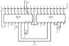
Does any one know - test a tachometer circuit with the lm2917-14pins and lm3914 that works?

i would like to make one for my 12v car using distributor braker points ..

i have found 1-2 but i saw that many had problems and i am not sure if actually working ..
in this one finaly the user (rude) argue and dont know if finaly make it work - https://www.electro-tech-online.com/threads/tach-signal-and-f-v-converter.103555/

Have a nice day

hi,
Do a SEARCH on this forum for LM2917 I have just checked, there's lots of info.:)
 
The datasheet for the LM2907/LM2917 says that the 14 pins version must be used with breaker points. The 8-pins version is used with a variable reluctance pickup that has an output that swings above and below ground.

The datasheet shows a tachometer circuit (using the 8-pins IC) but it is for a modern variable reluctance pickup. It also shows tachometer circuits (using the 14-pins IC) for 6 cylinder and 8 cylinder engines with breaker points which is what you need.

Your circuit has many useless parts including the diode that is not needed. You have a 500 ohm pot in parallel with a 500k pot and both are wired to blow up the LM29xx IC instead of just the 500 ohm pot wired as a volume control.

The 10k resistor at pin 7 of the LM3914 causes the LEDs to be very dim at only 1.5mA each. The two resistors on the LM3914 set the amount of input voltage that lights the 10th LED and their current sets the brightness of the LEDs.
 
Thanks both for the quick replies :)

ok i think that these ones schematics is what i need it


**broken link removed**


Lets say that i had a 6 cylinder 12volt car... i would use a lm7808 to supply the circuit
and i would take the voltage for the lm3914 input signal like this... right?


**broken link removed**


2 questions now....

1) what kind of part is this symbol ?


**broken link removed**


2) what we are doing if we have 4 cylinder car ??


Thanks again for the interesting
 
Lets say that i had a 6 cylinder 12volt car... i would use a lm7808 to supply the circuit
and i would take the voltage for the lm3914 input signal like this... right?
The LM2917 has a zener diode for its voltage regulator. the LM3914 will get hot and might be damaged by voltage spikes if it is powered from a vehicle's 12V so an LM7808 would be good if you use the input and output capacitors recommended in its dtasheet.

1) what kind of part is this symbol?
**broken link removed**
It is a meter for that circuit. Use the circuit shown for the 8 cylinder engine. The 10k resistor at its output can be a 10k volume control that feeds the input of the LM3914.

2) what we are doing if we have 4 cylinder car ??
It looks like the 100k pot needs to be changed to 200k.
 
Thank you my friend..

i will try to build it soon .... :)

ps: your avatar is very nice my favorite cartoon hero when i was child :) :)
 
Last edited:
Hi again my friends...

1 question :

the capacitors in the 2917 schematic i post it.. 0,02μf and 1.0μf are with polarity ??
the shop i use to buy electronics parts told me that there is not a 0,02μf with polarity (+/- ) only the 1.0μf is with (+/- )


can i use normal capacitors with no polarity?

thanks
 
depends on the accuracy... anything will work but aluminum electrolytic caps leak and drift, Y5V ceramics drift and are voltage sensitive. X7R or better ceramics for acceptable operation.

as i recall the 2917 "charge pump" is a multiplying current mirror that drives charge out pin 3 in relation to the charge demanded by pin 2 so BOTH caps are critical to proper operation.

while hardly necessary these days, a precision clamped wave can be used do the same thing if you drive an opamp integrator with it through a capacitor since total charge is voltage times capacitance times frequency

dan
 
Metalized plastic film capacitors are non-polarized, do not drift and are available in those small values at fairly low prices.
0.02uF is not a standard value anymore. Use 0.022uF which is labelled "22nF".
 
what is the difference between these two symbols ??

**broken link removed**

( this one i was knowing until know about capacitors symbol )


**broken link removed**

(the one that is used in the above schematics)


Has to do with the polarity of the capacitor ?? or the type of capacitor ?


this is what confuse me


thanks
 
Both of your symbols show non-polarized capacitors.
A polarized capacitor has its positive wire marked with a "+" sign on a schematic and on very old and tantalum capacitors. Modern capacitors have the (-) wire marked with a bar with --- in it.

You need to know about capacitor theory to know which type of capacitor to use where.
 
Thanks audioguru
now i can continue my project

yes i know that all are based in theory first and reading. i have download some books with the basic theory in electronics and have start reading them

thanks again
 
I follow all the suggestions and i complete my Circuit.

i test it to my car but in the output i was getting 5 volt . Nothing changed as i get higher rpm in my engine ( just only 0.45 volt but that had to do with the cars voltage and charging )

But i saw that i had forget to place the P-N diode

After i place it in my Circuit ( cross finger not burned my IC ) i get my results... i get 1 volt for every Rpm in my Output
1000rpm = 0,987-1 volt 2000rpm = 2 volts etc


Here is the Schematic for 4 cylinder cars

**broken link removed**


here is some pictures from my prototype and the test in my car ( with multimeter not lm3914 )

**broken link removed**

The trimer is 10k and it was placed instead of 10k resistance in the pin 5 of the Lm2917


**broken link removed**


car test

**broken link removed**

**broken link removed**


thanks all for the help !!!!!!!!!


If you have any suggestions to improve it ... will be here ;)
 
I am glad to hear that it works well.
I learned to drive in about 1965 in a VW Beetle similar to yours.
 
Nice to hear that :)

Is my lovely car and i restore it all by my self ;)
**broken link removed**


Back to the project

I took my LM3914 circuit ( i build it for testing.. thats why i have placed the 2 trimers instead of normal resistors ... so i will check what value of resistors should i use in the normal Lm3914 circuit depending the application)

**broken link removed**


i start my engine and make the adjustments for 500rpm / led


I notice that when i rise up the the rpm of my engine very quickly the leds go off (like drop rpms) for a second and then light again until the rpms the engine has ...

example :

the engine is in idle 1000rpm = 2 leds on
Accelerate normal until 2000rpm = 4 leds on
Accelarate until 3500 rpm very quickly / rapid the leds turn off (bar mode )one by one and then go on again until the rpm of 3500 = 7leds on


1) Why this is happen?
Any suggestion ?

( i have all ready a vdo tachometer in my car so i can check the rpm of my engine )

2) i have seen two lm3914 with 20 leds but in dot mode... can we use two LM3914 for 20 leds in Bar mode?
 
Last edited:
I don't know why your circuit drops the output voltage when the engine quickly revs.
Two LM3914 ICs can be connected in series in the BAR mode if the input has a divide by 10 or 10 times amplifier for one of the ICs input.
 
Thanks :D


i find in the net this schematic that must be what i was needing about 20 led bar mode ( values of resistors will be changed in my needs )

**broken link removed**
(click to enlarge)

The pin 9 (mode) in second lm3914 is not connected to nothing ? is this right in this schematic

...
 
You saved your schematic as a fuzzy JPG file type so I cannot read the resistor values. If you saved it as a very clear PNG file type then it would be crystal clear.
The MODE pin is disconnected from anything for the DOT mode. It is connected to the positive supply for BAR mode.

You posted it over at PhotoBucket instead of here. Sometimes it takes all day for Photobucket to wake up.
 
here is the picture my friend

:)
 

Attachments

  • ScreenShot059.jpg
    ScreenShot059.jpg
    42 KB · Views: 7,357
Your LM3914 ICs will get too hot and might melt because the supply voltage to the LEDs is very high and their current is fairly high at about 17mA.
If you use 1.8V red LEDs then the output transistors in the LM3914 have 13V across them and 17mA through them which is a dissipatipn of 0.22W. With 10 LEDs lighted then the heat in the LM3914 is 2.2W. Its absolute max allowed dissipation (when it is very hot) is 1.365W at room temperature and is less at higher ambient temperatures.
The datasheet shows how a resistor can be connected in series with the supply to the LEDs (and a capacitor) to share the heat.

R4 in your circuit does nothing and can be removed.

You need to fix the MODE pins. The datasheet shows a two-LM3914's circuit with a MODE switch.
 
Last edited:
Status
Not open for further replies.

Latest threads

New Articles From Microcontroller Tips

Back
Top