GrumpyMailMan
New Member
Greetings
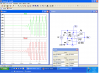
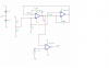
I've been trying to use two LF347 to generate triangle wave at 250 kHZ for a PWM.
But from the Tina simulation i could get is around 100kHZ and 160kHZ higher then that the waveform are distorted.
I've read a topic from other member in this fourm, but one thing I don't understand is how does the circuit starts up when there is no input to the circuit.
I understand the standard equation for this circuit is f=R2/(4*R3*C*R1), but it seems that over 100khz this is not valid.
Mainly
1. How can i fix the circuit so it can generate 250KHZ triangle wave without distortion
2. Why does the equation not valid when the frequency is over 100 KHZ
My possible guess
1. due to the slew rate?
2. noise feedback into the opamps
The data sheet given did not provide much information on hight frequency operating.
Wonder if anyone chould help me with it.
")