Continue to Site

Welcome to our site!

Electro Tech is an online community (with over 170,000 members) who enjoy talking about and building electronic circuits, projects and gadgets. To participate you need to register. Registration is free. Click here to register now.

  • Welcome to our site! Electro Tech is an online community (with over 170,000 members) who enjoy talking about and building electronic circuits, projects and gadgets. To participate you need to register. Registration is free. Click here to register now.

LEDs Sync To Music

Status
Not open for further replies.

FreeTrial

New Member
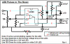
I want to sync LEDs to music through the audio jack. There was this tutorial I and I could not figure it out. It involved a TIP31, switch, power, LEDs, and a audio jack. I have pics, but i need someone to tell me whats wrong.

I have 3 LEDs, Yellow, 3v 20 mA
TIP31
2 Way Switch
9v Battery
Audio Jack Input

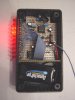
Would this work or is there an easier way. Because I tried and it didn't work.
Please Help!! :eek:
 
Sketch the schematic in MS Paint or something and attach it.
 
If the jack was from the output of a power amplifier then you are lucky that the amplifier or the TIP31 didn't blow up!
If the jack was from the output of an MP3 player then the signal voltage is too low to turn on the transistor.

1) The base of a transistor needs a current limiting resistor in series, and a diode to prevent too much reverse voltage.
2) LEDs need a current limiting resistor in series.
3) Why does your switch have 3 wires?
4) Your LEDs are not in series.
5) You don't show the polarity of the battery nor of the LEDs.
 
I see what you have done with the wiring:
You have the 3 LEDs in parallel and the switch connects either the transistor to them or connects them directly to the battery.
So the switch connected the 3V LEDs to the 9V battery and since they don't have current limiting resistors then they instantly burned out!
 
I can't see what connects to what in your fuzzy pics.
1) The battery and LEDs polarities are not shown.
2) You don't say if the input to the jack is about 10V from a power amp to a speaker, or just 0.1V from a CD or MP3 player, which makes a huge difference in the design.
3) No current limiting resistors are in your circuit.
 
maybe too simple?

Hi,

From the looks of those pics, these guys have made all the points I was going to make....simply connecting up an audio source to the base of a transisitor used to switch LED's may in fact work, but its a very crude way of doing things.
Audio source may blow your transistor...or not provide enough voltage for it (0.6 usually). And connecting LED's without any form of current limiting resistor will make em heat up, if not blow instantly (depending on your power source). LED's also have a voltage requirement...if you've got 3 1.8V LED in series...you need at least 3*1.8 = 5.4V to get them to light up.

Also, it leaves no room for improvements..like having a different colour LED for bass, middle and treble.

It might be a good idea to use a single stage opamp, setup as a comparator (or..a comparator for that matter :D ) that way you could add a potentiometer to adjust the 'sensitivity' so that your LED's flash nicely in time with the music. I would also add a diode on the input, along with a zener diode to protect your circuit against massive signal peaks (10v+).

Try google for 'clipping detector'. Its a circuit used to indicate when a signal input is too large, and needs attenuating. It turns on an LED when the input goes over a certain level (user adjustable). I think it does exactly what you are after.

An alternative, but still, very simple solution would be using logic...like a 74HC04 inverter or two. These inverters are quite handy for simple switching solutions and theres plenty of schematics on the net, using feedback resistors to change the sensitivity, add hysteresis. BOTH of the above solutions would probably need a power transistor for driving the LED's. It might not be necessary for a few LED's, but it'll allow you to connect more in the future, or higher current (brighter) LED's.

Its all about how simple, or complicated you would like to make it. Obviously simple is better (and cheaper) but I wouldn't go too simple or you'll be facing reliability issues.

My two pence.

Blueteeth.
 
People say that this circuit works well. It stretches the pulse width to make the LED more visible.
Use it with the line level or headphone output of a CD or MP3 player. It might blow up with an output of a power amplifier unless an attenuator is added to the input.
 

Attachments

  • LED music pulses-layout.PNG
    LED music pulses-layout.PNG
    28.6 KB · Views: 7,372
I appreciate all the help, it just the number of posts say exactly what I am, an electronics newby. I understand some of what your saying, but Im trying to stick the easiest way. When i saw a tutorial for this, this is what he used. I couldnt get mine to work though.

**broken link removed**
70733363_7bc5873491_o.jpg

Id like mine to work with MP3 and through my computer speakers.
Thanks.
 
The author of that terrible circuit doesn't know anything about electronics. Him and a few other people blew-up their TIP31 transistors and LEDs because the circuit doesn't have current-limiting resistors for the transistor and for the LEDs.
One guy says it works then stops. After a while it works again. I think his sound card heats up then stops because the transistor is like a short when it doesn't have a current-limiting resistor. He is lucky that the sound card stops when it gets too hot.
Many people complain that the LEDs don't light when the music is not loud because of the transistor's required turn-on voltage.
 
Try it and you'll like it.
Later I will show how to add a microphone to it so it is wireless.

I have a project with 20 LEDs in a bar-graph. It is sensitive enough to indicate a pin dropping on the floor on the other side of a room. It has a microphone and a rechargable battery. It flashes to the beat really well.
 

Attachments

  • Sound Level Indicator 002.jpg
    Sound Level Indicator 002.jpg
    47.1 KB · Views: 1,315
Ok ill try your circuit see how it goes..
Can you make a list of the materials, so i make sure I get this right.
I want like 3-4 LEDs and we'll say 2.1v LEDs.
ANd hopefully radioshack has all this..

And explain those teal lines and x's...
thanks
 
FreeTrial said:
Can you make a list of the materials, so i make sure I get this right.
It has only a few parts, you can make a list.

I want like 3-4 LEDs and we'll say 2.1v LEDs.
Then each LED needs a 180 ohm resistor in series with it, as shown in my circuit by the 220 ohm resistor. Use 1000uF instead of 220uF for 3 or 4 LEDs with resistors. Use a 1N4001 diode instead of the one I have shown.

And explain those teal lines and x's...
Stripboard has parallel copper tracks on it and is perforated. The lines are the tracks and the x's are where the track is cut with a drill bit. Stripboard is like a pcb where half the wiring is already done for you.
 
To avoid confusion, I'll just use your circuit for now, but here’s the list, I think that’s everything.

-Resistors (10k, 10k, 1k, 22k)
-Capacitors (.1, 470, 220)
-LM386<-------- what exactly is this, another name??
-9 Volt battery
-1 LED
-1n4148 diode
-Breadboard
 
FreeTrial said:
-Resistors (10k, 10k, 1k, 22k)
No. 10k volume control, 10 ohms, the 1k and 22k are correct. Don't forget to get a 180 ohm resistor for each LED.

-Capacitors (.1, 470, 220)
No. Capacitor values are in pF, nF, uF and even F.
Instead of the 220uF, use 1000uF if you have 3 or 4 LEDs.

-LM386<-------- what exactly is this, another name??
It is a 1/2W audio power amplifier made by National Semiconductor. RadioShack should have it.

-9 Volt battery
Instead, use a wall AC-DC adapter if you want. Get a battery connector if you use a battery.

-1n4148 diode
Use a 1N4001 diode if you have more than 1 LED.
 
:) Ok what capacitors do I need?

And how do i know the voltage of the capacitors, like some say different voltages?(Which one should I get?)

Possibly show me where to get a 10k vol control? Could not find one.

Whats the "R" next to the resistor?

And hopefully my final question, the resisitors should be __ohms, 1/4 watts?

:) :D :p :cool: :p :)
 
Last edited:
FreeTrial said:
:)Ok what capacitors do I need?
Their complete value in uF is on my schematic.

And how do i know the voltage of the capacitors, like some say different voltages?(Which one should I get?)
The power supply is 9V so use capacitors with a minimum voltage rating of 16V. 25V or 35V capacitors will also be fine.

Possibly show me where to get a 10k vol control? Could not find one.
You like RadioShack then use a RadioShack 10k volume control. Get a knob for it there too.

Whats the "R" next to the resistor?
Because its resistance must match the voltage rating of the LED as in the chart. You say your LEDs are 2.1V so use a 180 ohm resistor in series with each LED.

And hopefully my final question, the resisitors should be __ohms, 1/4 watts?
Yes. 1/2W is also fine but they are larger.
 

Attachments

  • volume control.PNG
    volume control.PNG
    23.6 KB · Views: 535
Last edited:
Thank you very much, hopefully this works, and everything goes fine. I might not start this until later on. I have to gather the needed 15$ or so. Ive bene making small project lately since its been a boring summer.

Thanks again.:p :p :p :p :p :p :p
 
Status
Not open for further replies.

New Articles From Microcontroller Tips

Back
Top