Hi Suraj,
It seems you have the correct procedure. You need to keep track of the row number and select the correct five bytes (40 bits) of data from your display array during each interrupt. You'll clock out those 40 bits into the daisy-chained shift registers, blank the display, latch the shift register data onto the outputs, then select the new row to turn the display back on. You do this procedure each interrupt to display a new row.
Regards, Mike
Hi Thanks for the help mike.
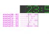
From your reply I noticed that you have only 5 registers (5bytes) for the 40 column display not 40 registers like I do.