Continue to Site

Welcome to our site!

Electro Tech is an online community (with over 170,000 members) who enjoy talking about and building electronic circuits, projects and gadgets. To participate you need to register. Registration is free. Click here to register now.

  • Welcome to our site! Electro Tech is an online community (with over 170,000 members) who enjoy talking about and building electronic circuits, projects and gadgets. To participate you need to register. Registration is free. Click here to register now.

LED SignBoard 64X8 - PIC 16F628A

Status
Not open for further replies.

Gayan Soyza

Active Member
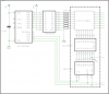
LED Sign Board 64X8 - PIC 16F628A

Here is a recent signboard I have designed under a PIC 16F628A, 4MHz.

It’s a 64 X 8 led matrix board (64 columns & 8 rows).

Didn’t work much hard with code stuff. Just added some basic scrolling.

I cannot resist I want to show what I had in my mind.

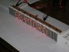
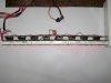
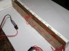
Here is a video of my project & some pictures of that.(Photography from - Pasans camera)

Light - YouTube - SignBoard Light

Dark- YouTube - SignBoard Dark
 

Attachments

  • Sign 64X8 Front.jpg
    Sign 64X8 Front.jpg
    82 KB · Views: 4,009
  • Sign 64X8 Top.jpg
    Sign 64X8 Top.jpg
    68 KB · Views: 1,535
  • Sign 64X8 Back.jpg
    Sign 64X8 Back.jpg
    86.3 KB · Views: 1,792
Last edited:
Very nice! Do you have a schematic to show how you did the multiplexing?

It looks great.
 
Very nice Gayan.

I would like to see the schematic too just to see how you're latching column data.

Mike
 
Last edited:
Thanks guys.

I was making some boxes these days actually its harder than designing the project.

Reg brightness you can still reduce the 47R resister but I wont' recommend.Don't know when uC will stop run & the particular column would be blown :O

With column scanning method I'd like to add some more columns & see if its fine then ok otherwise shift to row scanning technic.
 
Last edited:
hey Gayan can you write some notes on the operation of this signboard. I know it may seem like a silly question but how did you center the text? was it like a auto center or was it manual? Manual being you typed spaces to make it looked center?

Do you mind if i use this design? If i was to ever make any money from something i use from someone else i would of course give them some royalty if you understand :)
 
Hi AtomSoft

First of all you need to multiplex your display what ever the method you like.
The two methods I use is column scanning & row scanning. You can do that using shift registers or using direct I/O ports.
The above project I used a column scan because it has only 64 columns. If I have 100 columns & above then I might do a row scanning method.

In column scan I’m scanning one column at a time like multiplexing SSDs.
Load 1st column –show for a while—turn off previous column—load next column-- show for a while-- turn off previous column--…………………
If you have 5 columns then you need 5 column registers.
If you have 20 columns then you need 20 column registers.

The column registers contains data or pattern. When you multiplexing rapidly then the data will show on the matrix display.

I think the above things you know very well.

Regarding balance (centering) you don’t need special code to do that. For a 5 column display if you want to show only the middle column, you need to turn off (clear) the 1st, 2nd, 4th, 5th column registers & leave the 3rd column with data. So when multiplexing rapidly it will show only the middle column data.

When a letter moves from right to left I use a “Shift Count Register” so it’s easily to place the text on what ever the place you like.
 
While Gayan's 1/64th duty cycle matrix seems to work well, I would recommend scanning rows at a 1/8th duty cycle instead to improve brightness and better manage 'peak' current requirements. You could do this by replacing the 74HC164's with 74HC595's + ULN2803's, or better yet use TPIC6C595's or MIC5821's or one of the other serial-to-parallel sinking driver IC's. Then remove the current limiting resistors from the row driver and put them on the column drivers.

Mike
 
Last edited:
ok how about for controlling BI-Color LEDs Matrixs. I have 5x7 Matrix LED but they are BI color. Some info:

Orange red and yellow green

Unit is column cathode
row anode

Can you tell me or give me your opinion on the best way to control this? Im sure i can add or alter it for Many without issue but thoughts would be nice.
 
Status
Not open for further replies.

Latest threads

New Articles From Microcontroller Tips

Back
Top