I have made LED-lights for my car (dome-light, instrument cluster, HVAC, etc) to replace the stock bulbs. Although I have not installed any of these “bigger” units yet I have had a few test-series of LEDs connected in the car for some time. These are all still in good working condition.
Before installing the bigger pieces in the car i wish to take advice from people who know this alot better than me =)
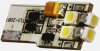
The LED-lights are comprised of many series of 3 LEDs. Each series has a separate resistor. The LEDs Vf range from 3 to 3,5v and most are 30mA (they are standard high-intensive and not luxeon-stars or the like).
The issue here is the cars DC output vs the LED arrays resistors etc...
I have a scantool/datalogger software hooked up to the car and have monitored the voltage with alternator both on and off.. With alternator off, i get 12,5-12,8v.. and when its on i get around 13,7-13,8v.
I have googled and read alot and the biggest problem with car voltage in general seems to be "voltage spikes". Some say these spikes can become up to 150v..!
Although i have logged the car for hours and hours i have never seen a spike, but maybe i need an oscillator or something to see that properly.. But how big are the chances of a spike in a new car? Is it like once a day or week? Or is it more like "it could happen maybe if you were driving 350mph and lightning struck your car"?
Fact remains though that the test-LEDs are still working good...
My initial plan was to use LM317 to regulate the voltage to 11v - which would provide 11v for the LEDs both during alternator off and on. However 11v gives LM317 1,7v headroom when alternator is off and 2,7v when when its on.
I do realize that 1,7v may not be good enough and thats why im asking for help, because i dont want to waste time building something that wont work... How does the LM317 act when Vin drops below the required Dropout voltage headroom? Does Vout become 0 or does it just decrease – making the LEDs dim?
Would it be better/simpler to just design the LED-arrays for 14-14,5v and accept that they become abit dimmer when alternator is off? But then its the possible "spikes"... I just cant see a perfect solution, but can accept a compromise..
Before installing the bigger pieces in the car i wish to take advice from people who know this alot better than me =)
The LED-lights are comprised of many series of 3 LEDs. Each series has a separate resistor. The LEDs Vf range from 3 to 3,5v and most are 30mA (they are standard high-intensive and not luxeon-stars or the like).
The issue here is the cars DC output vs the LED arrays resistors etc...
I have a scantool/datalogger software hooked up to the car and have monitored the voltage with alternator both on and off.. With alternator off, i get 12,5-12,8v.. and when its on i get around 13,7-13,8v.
I have googled and read alot and the biggest problem with car voltage in general seems to be "voltage spikes". Some say these spikes can become up to 150v..!
Although i have logged the car for hours and hours i have never seen a spike, but maybe i need an oscillator or something to see that properly.. But how big are the chances of a spike in a new car? Is it like once a day or week? Or is it more like "it could happen maybe if you were driving 350mph and lightning struck your car"?
Fact remains though that the test-LEDs are still working good...
My initial plan was to use LM317 to regulate the voltage to 11v - which would provide 11v for the LEDs both during alternator off and on. However 11v gives LM317 1,7v headroom when alternator is off and 2,7v when when its on.
I do realize that 1,7v may not be good enough and thats why im asking for help, because i dont want to waste time building something that wont work... How does the LM317 act when Vin drops below the required Dropout voltage headroom? Does Vout become 0 or does it just decrease – making the LEDs dim?
Would it be better/simpler to just design the LED-arrays for 14-14,5v and accept that they become abit dimmer when alternator is off? But then its the possible "spikes"... I just cant see a perfect solution, but can accept a compromise..