Hey. My name is Frank and I am pretty new to electronics etc...
I have this idea, which I know has already been done, but this is my version of it: A light switch on your wall that activates a speaker on your keys so you can find them.
The way I am trying to do it is with a remote control car - The light switch hits the button on the controller and sound emits from a buzzer speaker that is soldered to the car circuits. Basically I am trying to solder the buzzer speaker somewhere to activate it when the switch is turned on. But where?!
Any other ways of achieving this would be much appreciated!
Here are some photos to show you what I am on about:
The car
**broken link removed**
The controller open
**broken link removed**
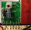
The car open
**broken link removed**
The buzzer soldered with no luck..
**broken link removed**
Thanks very much.
-Frank
I have this idea, which I know has already been done, but this is my version of it: A light switch on your wall that activates a speaker on your keys so you can find them.
The way I am trying to do it is with a remote control car - The light switch hits the button on the controller and sound emits from a buzzer speaker that is soldered to the car circuits. Basically I am trying to solder the buzzer speaker somewhere to activate it when the switch is turned on. But where?!
Any other ways of achieving this would be much appreciated!
Here are some photos to show you what I am on about:
The car
**broken link removed**
The controller open
**broken link removed**
The car open
**broken link removed**
The buzzer soldered with no luck..
**broken link removed**
Thanks very much.
-Frank