Continue to Site

Welcome to our site!

Electro Tech is an online community (with over 170,000 members) who enjoy talking about and building electronic circuits, projects and gadgets. To participate you need to register. Registration is free. Click here to register now.

  • Welcome to our site! Electro Tech is an online community (with over 170,000 members) who enjoy talking about and building electronic circuits, projects and gadgets. To participate you need to register. Registration is free. Click here to register now.

JOB: Convert schematic to eagle+gerber

Status
Not open for further replies.

fuper

New Member
Hi - hope this is cool to post in this forum. Seemed the closest match.

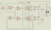
I need the following schematic:

https://www.aaroncake.net/circuits/stepper.gif

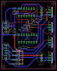
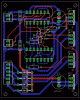
Converted to eagle such that i can send off the gerber files to a PCB house.

I am willing to pay. I would need a guarantee that I could successfully get a usable PCB.

I will donate the end result to open source.
 
Is S1 a switch? Have you tried this? Don't you get switch bounce? (multiple steps if the switch does not close cleanly)
 
I am willing to pay. I would need a guarantee that I could successfully get a usable PCB.

The origin of this circuit can be found here for anyone curious. The only way to be sure the circuit will work and work well would be to breadboard it and actually run it under various conditions. Unless the circuit is really run there is really no way anyone can guarantee or promise anything.

Ron
 
Is S1 a switch? Have you tried this? Don't you get switch bounce? (multiple steps if the switch does not close cleanly)
The switch only connects through to the JK inputs; the state of these doesn't affect the output until the flipflop is clocked (via the STEP line).


op: As far as getting a pcb drawn up... there's a member of this forum that seems to do that a bit just for the fun of it, maybe they'll read this thread.
 
@fuper,
better breadboard the circuit and check
who would give such guarantees, you see !!
 
Let me give some more information -

I've breadboarded the circuit. It works fine driving a unipolar stepper motor.

S1 "Direction" will be removed. Direction will be an external input like Step.

The circuit will be part of an open source CNC router. Therefore Direction and Step will come from buffered and isolated external signals either a parallel port or micro controller.

The PCB will need 4 stand-offs so I can use a #4-40 screw [US, not metric] to mount it.
The Stepper will be under 2 amps MAX. More likely 1 amp.
The input/output connections will be .1" molex KK connectors. Total of 3 parts:
2 pin for power
2 pin for direction/step
6 pin for stepper
You have experience designing PCB professionally and advise me on best practices.
Design the board so I may optionally attach a heat sink onto the TIP31 transistors.

The full page for the circuit is:

https://www.aaroncake.net/circuits/stepper.asp

The guarantee I spoke of was more for the PCB to be technically correct and submittable to a PCB house.
 
Last edited:
One member who I see make boards quite a bit is Boncuk. Maybe he will wander in and offer some help.

Ron
 
here are the files. don't bother about the un-routed list , if it shows.
Gerber creation, you may try for yourself. The facility exists in the software.

Perhaps , by my making, you lost a chance to learn Eagle.
 

Attachments

  • FuperStepper.zip
    61.9 KB · Views: 396
Last edited:
Hey - Mvs Sarma -

I appreciate the offer and I don't want to take advantage of your kindness. I prefer to pay for this job so I can get exactly what I want. While your circuit is excellent it does not meet all of my requirements I'm afraid.

Shane
 
Hi Shane,

I simulated the circuit and it works fine.

Free wheeling diodes are omitted since the circuit simulator won't produce any back EMF. :D

If you use remote signals for step and direction make sure the connected IC always "see" some level at their inputs (U1, pin12 and pin6) as well as U2 pins3 and 13.

I suggest to use pull down resistors for a defined level at the mentioned input pins.
 

Attachments

  • STEPPER-CONTROL.gif
    STEPPER-CONTROL.gif
    12.2 KB · Views: 1,576
Here is a PCB suggestion.

It contains everything you requested + pulldown resistors.

If they are not needed just don't use them.

Boncuk
 

Attachments

  • STEPPER.gif
    STEPPER.gif
    26.8 KB · Views: 546
The step and direction are remote signals. There will be no switch. Yes I had direction floating at one point while debugging and it was a bit erratic!

Pull downs are a good idea.

PS - what type of software are you using?
 
Ah just re-read "Suggestion"

The board looks good! Would need the power moved away from the step/direction as I worry about the noise.

Could the board be made smaller? Also I think the caps are a nice addition. I had a couple of caps on my breadboard originally because my power/noisy breadboard where suspect but now that you did this I realize the draw on a stepper is large and it is safer to go this route.

Thanks
 
Hi Shane,

of course could the board be made smaller. I just kept a minimum distance between power transistors (out of experience) for optimum cooling.

The power connector has been moved North.

Boncuk
 

Attachments

  • STEPPER.gif
    STEPPER.gif
    24.2 KB · Views: 1,282
Thanks much Boncuk!

This design looks perfect. I see the pull downs on the inputs with the 2 10k resistors which is a great suggestion along with the caps as well as the movement of the step/direction connector.

When you post the eagle files I'm going to send for a small batch of boards probably using batchpcb.com. It's a low cost way to get a few boards. $10 + $2.50 per inch^2 or there abouts.

Let me know if you want one I can mail em to you.

Oh would it be possible to add a revision # and your name or something? :)

Thanks again so much!
 
Last edited:
Hi Boncuk,

Nice board!

Could you explain the theory behind the C3 and C4 capacitors? Are these decoupling capacitors like the 2 other ones? Wy this size and wy 2 instead of 1 or 4?

Thanks!

Alain
 
Hey Bonuck -

I'm ready to pull the trigger on getting a few PCB made - can you post the original files at your convenience? The company I'm using needs gerbers with the layers identified. Thanks!

Fuper
 
Final files

As promised - here are the Schematics and PCB layout provided by Boncuk. They are in the public domain free for anyone to use.

**broken link removed**
 
Well I got a couple of boards made. Put it together and of course it doesn't work :( I'm hopefully just tired and missing something obvious. However all the output signals remain fixed. I spent a fair amount of time checking the traces and everything appears to be fine. I did continuity checks as well on a bunch of traces looking for bad solder joints.

Any suggestions?
 
Status
Not open for further replies.

New Articles From Microcontroller Tips

Back
Top