Hello,
We need a 2kW load bank so that we can do full-load-to-no-load transient testing on our 2kW SMPS. Also, We also need this load bank to load the SMPS with to see if the SMPS is stable. As you know, Electronic loads cannot be used for this purpose, because they have an effective capacitance, and that effects the SMPS's feedback loop parametrics, so obviously electronic loads cannot be used in this cause.
So anyway…
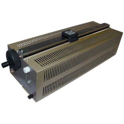
Do you agree that the attached 2kW resistive load bank is the best way to actually make such a load bank?
The Twenty-four TO247 power resistors are LTO series
LTO series TO247 resistors:
https://www.farnell.com/datasheets/1817173.pdf
The reason the attached load bank is the best way to do a resistive load bank is because…
1..The TO247 resistors are simply & quickly removed and replaced by simply unscrewing and desoldering the legs off the surface mount pads. –Therefore, you can quickly and easily change it to get almost exactly what resistance value you want.
2…The fan means that the load bank occupies a small volume.
3…The PCB on which the resistor legs are soldered on to provides the connections between the resistors, so you don’t need to fiddle with multiple wires and connections. (this ‘connection’ PCB is screwed to the heatsink)
4…There are solder blob pads across each resistor, so any resistor can be quickly shorted out by just “blobbing” solder across these pads.
We need a 2kW load bank so that we can do full-load-to-no-load transient testing on our 2kW SMPS. Also, We also need this load bank to load the SMPS with to see if the SMPS is stable. As you know, Electronic loads cannot be used for this purpose, because they have an effective capacitance, and that effects the SMPS's feedback loop parametrics, so obviously electronic loads cannot be used in this cause.
So anyway…
Do you agree that the attached 2kW resistive load bank is the best way to actually make such a load bank?
The Twenty-four TO247 power resistors are LTO series
LTO series TO247 resistors:
https://www.farnell.com/datasheets/1817173.pdf
The reason the attached load bank is the best way to do a resistive load bank is because…
1..The TO247 resistors are simply & quickly removed and replaced by simply unscrewing and desoldering the legs off the surface mount pads. –Therefore, you can quickly and easily change it to get almost exactly what resistance value you want.
2…The fan means that the load bank occupies a small volume.
3…The PCB on which the resistor legs are soldered on to provides the connections between the resistors, so you don’t need to fiddle with multiple wires and connections. (this ‘connection’ PCB is screwed to the heatsink)
4…There are solder blob pads across each resistor, so any resistor can be quickly shorted out by just “blobbing” solder across these pads.
")