Continue to Site

Welcome to our site!

Electro Tech is an online community (with over 170,000 members) who enjoy talking about and building electronic circuits, projects and gadgets. To participate you need to register. Registration is free. Click here to register now.

  • Welcome to our site! Electro Tech is an online community (with over 170,000 members) who enjoy talking about and building electronic circuits, projects and gadgets. To participate you need to register. Registration is free. Click here to register now.

IRFU9020, How fast?

Status
Not open for further replies.
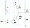
Im only drawing about 10mA. Unfortunately I dont have the space for AA cells.I do plan on using Nimh Button cells though. I was going to use 7 connected in series giving me 10.1v @ full charge, Im using it in a different variation of this circuit, where Im using the PicAxe as a power switch for a 555.
 
If it's just 10mA then why not just use a PNP transistor?

The circuit for driving one from a PIC is shown below.
**broken link removed**
 
Like I said I am just playing around w/ this. Seeing what I can, and cant do with different components, and configurations. Right now Im using an N-chan(2n7000) to pulse the (-) side of the circuit, but would rather pulse the (+) side. I was going to use an NPN, PNP similar to the schematic you posted, but Ive been playing with these MOSFETS lately and was curious if I could get the same result.
 
You could replace T2 with a MOSFET and remove R3 but R2 will form an RC circuit with the MOSFET's gate capacitance which will slow the off time too much for 30kHz operation.

If you want to drive your MOSFET at high speed, you need a MOSFET driver. You can use a special IC (recommended) or build your own from a few transistors (see attachment). In this case you only want to pulse the load at 10mA so it's not worth going to all the trouble, even more so considering the driver uses nearly as much current.
 

Attachments

  • MOSFET Driver.GIF
    MOSFET Driver.GIF
    7.1 KB · Views: 173
I was playing around last night using an N-chan (2N7000) and a P-chan(IRFU9020), set up similar to the first schematic you posted, and had very good results. Using my 10v batt pack, I got an output of 9.82v @ 30.2KHz w/ a 6.28mA draw from the batt. The batt only dropped <1v after a full run(10 min pulse 4x, 20 min pause between pulses, then complete shut down of the circuit) then Im using the same setup(N,P-chan) for the power hold on the PIC. Ill draw the schematic later.
 
Status
Not open for further replies.

New Articles From Microcontroller Tips

Back
Top