Continue to Site

Welcome to our site!

Electro Tech is an online community (with over 170,000 members) who enjoy talking about and building electronic circuits, projects and gadgets. To participate you need to register. Registration is free. Click here to register now.

  • Welcome to our site! Electro Tech is an online community (with over 170,000 members) who enjoy talking about and building electronic circuits, projects and gadgets. To participate you need to register. Registration is free. Click here to register now.

inverting amplifier - feedback help

Status
Not open for further replies.
Hello, for my college homework I have been given a task.

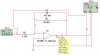
The circuit is an op-amp and it must have gain of -6 at 1kHz
It must have a gain of -3 at 9.6kHz.

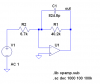
The input resistor is 6.7kohm, we must work out the value of the feedback loop - this consists of a capacitor and resistor in parallel.

I know that at 1kHz it must have an impedance of 40.2kohm
and at 9.6kHz it must have an impedance of 20.1kohm

Can anyone give me a solution of how to do it and please just dont give me the straight answer - I want to see how you did it.

Thanks
 
Simply calculate the value of the resistor and capacitor from calculating the individual required capacitive reactance.
 
Thats what Im trying to do but a bit unsure how to do it.

I will explain a bit more clearly

A capacitor and resistor are in parallel.
at 1kHz they have a impedance of 40.2kohm
at 9.6kHz they have an impedance of 20.1kohm

How would I work them out, would it involve a simultaneous equation
 
I would just do a couple of "trial and error" calculations to get close to what is needed.
The reactance of the capacitor at 1kHz will be much higher than at 9.6kHz.
A gain difference of only two times is needed so the capacitor does very little.
 
Thats what most of my friends are doing, I'm half way through solving a simultaneous equation to find these results, if it goes wrong I will resort to trial and error.

I will post my results If I solve it.

edit:

I have re-read my question and it says that must show all working, can anyone point me in the right direction with an equation - I'm really stuck
 
Last edited:
Hello vonsproken,

your answer depends on the precision wanted. At first, you can solve it in a very simplified manner, using a bode plot of the circuit. This circuit your professor proposed is a simple active low-pass filter. After the pole of the circuit, there'll be a slope of -6dB per octave, right? So, if there's a pole located one octave below the 9.6kHz frequency (that means, if there's a pole at 4.8kHz), the passband gain will be 6db higher than the gain at 9.6kHz. The big problem here is that these approximations aren't good enough because the frequencies involved aren't more than a decade apart, what makes the bode approximation a little bit lame. The engineer's solution: as we know that, near the pole, the gain decreases more quickly than the asymptote, if we place the pole a little bit after 4.8kHz, say, at 5.5kHz (keep in mind that this 5.5kHz is a wild guess =P), everything will be fine.

On to the calculations:
To achieve a passband gain of 6, the resistor in the feedback network should be 40.2kΩ.
The cut-off frequency is: fc = 1/(2*pi*R*C), and the values of R and fc are known (40.2k and 5.5k). Solving it for C, the formula yields: C≈720pF.

As everything until now were wild guesses, it is good to simulate the circuit just to see if all of this is not completely wrong. I used LTSpice to simulate the circuit, and got the following results:
  • Gain at 1kHz = 5.9
  • Gain at 9.6kHz = 2.97

Remember that all of this depended a LOT on my guess of the right location for the pole... And as the pole is very near 1kHz, the gain at this frequency will be certainly lower than 6. If we raised a little bit the value of the resistance, the values probably would be better. But again, this are all guesses, and in a real application you would have a bigger constraint: the commercial values.


But if you really want to calculate it, solve the equations. It isn't too difficult, but it demands more effort. Again, it really depends on what does your professor want. I had both kinds of professors at college: the practical ones, that would love a solution like this, and the math-lovers, that woud find it hideous. ;)

Hope it helped.

Castilho.
 
Thats what Im trying to do but a bit unsure how to do it.

I will explain a bit more clearly

A capacitor and resistor are in parallel.
at 1kHz they have a impedance of 40.2kohm
at 9.6kHz they have an impedance of 20.1kohm

How would I work them out, would it involve a simultaneous equation


Here's the way the procedure would go:

Write the transfer equation for the amplifier circuit, which includes the input resistor, the feedback resistor, and the feedback capacitor with an input of 1v. At this point the input resistor is known and R and C are not known.
Next, calculate the amplitude, which gives you an equation in F, R, C, and Gain (F is the frequency).
Now write two equations using that one equation, where in one F=1k and Gain=-6 and the other F=9.6k and Gain=-3. We now have two equations, but they will end up having a cross product of R and C so we simplify one of them in such a way so that when we subtract the two we get rid of the cross product and end up with an equation, which when solved, gives us the value of R.
Now we solve one of the equations for C and we calculate C knowing that R. That gives us both C and R so we're done.

Just to note, the magnitude of the feedback impedance is not R/(2*pi*F*R*C+1). The feedback impedance is complex and so has to be dealt with accordingly.

If you need a worked out example or would like to compare your result to a result that is known to work the way you need it to, just let me know (theoretically perfect, numerically to about 14 digits or so).
 
Last edited:
Hi, thankyou all for your input and your explanations.

The frequency at 9.6kHz is the breakpoint frequency hence half the gain - I didnt really make it all clear enough.

We used the simple equation breakpoint freq = 1/ 2piRC

So thats C = 1/2pifR

The resistor is what I use in the feedback in parallel with the capacitor, basically the resistor becomes the 40.2kΩ. Therefore using the equation above I get a value of 412.4pF.

This gets me a gain of -6 at 1kHz and a gain of -4 at 9.6kHz according to multisim

In theory I should get a gain of -3. I should get an Xc of 40200Ω which in parallel with the resistor makes it 20100Ω which should give me a gain of -3. Is this just because multisim is useless or is my working wrong.

This is how the teacher told us to do it. I have attatched my circuit diagram.
 

Attachments

  • my circuit.jpg
    my circuit.jpg
    27 KB · Views: 738
Rf=40.878k
Cf=718.21pF

Have you worked out the solution yet?
I'm giving you the answer because I doubt your teacher will accept it unless you show your method.
MrAl gave you hints as to the method.
I'll pretty much guarantee that Multisim is not wrong, although I don't have it on my computer (I have LTspice).
 
Last edited:
Hi, thankyou all for your input and your explanations.

The frequency at 9.6kHz is the breakpoint frequency hence half the gain - I didnt really make it all clear enough.

We used the simple equation breakpoint freq = 1/ 2piRC

So thats C = 1/2pifR

The resistor is what I use in the feedback in parallel with the capacitor, basically the resistor becomes the 40.2kΩ. Therefore using the equation above I get a value of 412.4pF.

This gets me a gain of -6 at 1kHz and a gain of -4 at 9.6kHz according to multisim

In theory I should get a gain of -3. I should get an Xc of 40200Ω which in parallel with the resistor makes it 20100Ω which should give me a gain of -3. Is this just because multisim is useless or is my working wrong.

This is how the teacher told us to do it. I have attatched my circuit diagram.

Yup, you'd get that result treating the Xc as another resistor, but the capacitor is reactive! When one takes into account the phase angle, the j in the complex plane, the Xc is not constant like resistance through one cycle at a given frequency.

When I worked it, I got a little different answer than Roff because I rounded to standard E48 and E96 values; C=715pf and R=41.2k. Close enough for 10 of 10 for both of us if I were back in the classroom in front of the podium.

The reason the Multisim results didn't match the calculated results is not the fault of Multisim, but rather the fault of the approach. The difference between a gain ratio of 2, the desired result, and that of 1.5, the Multisim result, is ~2.5db. That is far from the mark. That puts the 6db rolloff out at about 13khz rather than 9.6khz; right where using C = 1/2pifR to resolve the problem would put it.
 
Hi, I'm only in my first year at college so have done very little on phase angle and reactance. The teacher only requires that I do it the way shown above, same as this website

**broken link removed**

Although saying this I will still work out the proper theory to it, just give me later tonight and I will show you my attempt - lots of other assignments to get done aswell.
 
Your link shows the low pass filter you described with the equation you used. Note that the equation cited is for the "corner frequency" of the filter, the 3db point in the rolloff. The note even describes the value at that point as .707 of Vin. (db = 20log Vmeas/Vref=20log .707=3db

The criteria you described initially set the gain ratio at the two frequencies at 0.5 (3/6) with Vref at 1khz and Vmeas at 9.6khz . That is -6db not -3db. Did your instructor give you the wrong information for this problem or did it get jumbled in the translation?
 
Hi, I totally messed up and misread the question, some reason I was thinking that the breakpoint frequency was half the voltage gain - I just looked through a past assignment and realised that it was 0.707 (1/ √2) of the input voltage.

So my working and results are correct because I get an output of aproximately 4V, 0.707 x 6V = 4.24V

Thanks, if you had not pointed out my error I would have still been racking my brain.

I would like to thank everyone for helping me even though what I was asking was totally different to what I was needing, thanks MrCecil, MrAl and Castilho.
 
Your results are not what I get by using the breakpoint method. See attached.
 

Attachments

  • vonsproken's op amp problem.asc
    1 KB · Views: 251
  • vonsproken's op amp problem sch.PNG
    vonsproken's op amp problem sch.PNG
    9.2 KB · Views: 342
  • vonsproken's op amp problem bode.PNG
    vonsproken's op amp problem bode.PNG
    33.7 KB · Views: 323
Your capacitor value is twice that of mine.

1 / 2 x pi x 40200 x 9600 = 412.4pF
Yours is wrong. The RC feedback rolls off at 6dB per octave. To get 6dB attenuation at 9.6kHz relative to the DC gain (your teacher used 1kHz), your breakpoint needs to be an octave below 9.6kHz, i.e., 4.8kHz. Did you study the graph I posted?
 
Last edited:
Hi, I totally messed up and misread the question, some reason I was thinking that the breakpoint frequency was half the voltage gain - I just looked through a past assignment and realised that it was 0.707 (1/ √2) of the input voltage.
You probably remember someone saying it's the half-power point, which is the 1/√2 voltage point.
 
Hello again,


There are several approaches to this problem, at least three i can think of offhand:
1. Parallel Impedances (approximation)
2. Pole Placement with initial Parallel Impedance calculation (approximation)
3. A full circuit analysis and determination of R and C explicitly (exact)


I think the teacher is looking for #1, parallel impedances, according to the posts i have read so far. Interestingly, that's the least accurate method but perhaps a good starting place for a student.

Lets take a look at these three in a little more detail, but first, lets start with an analysis of the entire circuit solving for the amplitude so we can quickly check any proposed solution set of R and C.

With R and C unknowns and R1 the input resistor of 6.7k, we have the exact amplitude:
VoutAmplitude=(Vin*R)/sqrt(4*pi^2*C^2*F^2*R^2*R1^2+R1^2)

and note this is for any R, C, R1, F, and Vin. To solve for the gain, we make Vin equal to 1 and we get:
Gain=R/sqrt(4*pi^2*C^2*F^2*R^2*R1^2+R1^2)

With this equation we can check any answers we might obtain using whatever method we choose, and at frequencies of F1=1kHz and F2=9.6kHz.

Ok, now lets look at the method of parallel impedances. Here we approximate the parallel impedance at F1 at 40200 as that seems to be what the teacher wants and divide by R1 to get the approximate gain.

First the reactance of C for both frequencies F1 and F2:
Xc1=1/(2*pi*F1*C)
Xc2=1/(2*pi*F2*C)

and the parallel impedance for both these frequencies is:
Z1=R*Xc1/(R+Xc1)
Z2=R*Xc2/(R+Xc2)

and the gain for both frequencies is:
Gain1=Z1/R1
Gain2=Z2/R1

Now solving these equations for C knowing Z1=40200 we get:
Z1=40200
Z2=Z1/2
C=(Z1-Z2)/((2*pi*F2-2*pi*F1)*Z1*Z2)

and after plugging in the values we get a value for C:
C=4.603579286471579e-010

Now solving for R we get:
R=Z1/(1-2*pi*C*F1*Z1)

and after plugging in the values again we get:
R=44925.7275866702

Now using the gain equation above to check our results we get:
G1=6.54
G2=2.78

so we didnt get 6 and 3, but we did get an approximation.


Ok, so now lets turn to the pole placement method.
To do this, we recognize that at the pole frequency the first order response will be about 3db down, but we need 6db down (a gain of 3 is one half of 6), so we approximate the gain at twice the frequency as -6db so that means we can place the pole at one half the required frequency. One half of 9.6kHz is 4800Hz so we place the pole there. To calculate the resistor, we approximate using the parallel impedance method for F1, and that gives us the same value of R as before:
R=45489.4736842105

Next, we calculate the capacitor:
PoleF=4800
C=1/(2*pi*PoleF*R)

and we get:
C=728.9e-12

Now we want to check this result using the gain equation above, and we get:
G1=6.45
G2=3.04

which isnt too bad i guess.


Now lets go for the exact method using an exact analysis of the circuit.

Starting with the gain equation:
Gain=R/sqrt(4*pi^2*C^2*F^2*R^2*R1^2+R1^2)

we then form two equations for gain 1 and gain 2 at F1 and F2:
G1=R/sqrt(4*pi^2*C^2*F1^2*R^2*R1^2+R1^2)
G2=R/sqrt(4*pi^2*C^2*F2^2*R^2*R1^2+R1^2)

There are a couple ways to solve this, here we solve the first equation for C and then insert that result into G2 and then simplify and solve that for R. We end up with an equation that is void of C so we can calculate R from that and then insert that result into the first equation and get C. That will give us both C and R.

After solving in this way we get:
R=G1*G2*sqrt(F2^2/(F2^2*G2^2-F1^2*G1^2)-F1^2/(F2^2*G2^2-F1^2*G1^2))*R1
C=sqrt(R^2-G1^2*R1^2)/(2*pi*F1*G1*R*R1)

Now all we have to do is plug the values into the first equation to calculate R, then plug that and the other values into the second equation and solve for C. Doing this, we get:
R=40878.2618
C=718.211819e-012

and those two are very nearly exact, however we still check using the gain equation and we get:
G1=6.00000000
G2=3.00000000

which to that number of digits is exact.
 
Last edited:
Status
Not open for further replies.

Latest threads

Back
Top