Electro Tech is an online community (with over 170,000 members) who enjoy talking about and building electronic circuits, projects and gadgets. To participate you need to register. Registration is free. Click here to register now.
Welcome to our site! Electro Tech is an online community (with over 170,000 members) who enjoy talking about and building electronic circuits, projects and gadgets. To participate you need to register. Registration is free. Click here to register now.
I have to write a lab report about an inverting amplifier specifically the 741 op amp and we are investigating the frequency response.
so for the theoretical voltage gain i got -10 and i got 10 for the actual gain i am not sure if that is any where near correct.
Your calculation is correct. In an inverting amplifier the gain is determined by the ratio of Rf/Rin. If you measured a gain of 10, instead of -10, then your meter probes were probably backwards.
Just to expand on what Mat has just said,
the minus sign indicates that the amplifier is inverting.
If you are using a sine wave to measure the gain rather than a DC signal, "reversing the leads" will not make much difference.
If you are using an oscilloscope to look at the input and output signal, you will see that they are out of phase with each other.
Yeah i used an oscilloscope to look at the output at different frequencies this leads to another question i have.I tried to plot a graph of gain(dB) against frequency and we are given a graph to use as an indication however my graph turned out nothing like it
Yeah i used an oscilloscope to look at the output at different frequencies this leads to another question i have.I tried to plot a graph of gain(dB) against frequency and we are given a graph to use as an indication however my graph turned out nothing like it
At the following frequencies I got 1.93V for 1Hz,3Hz,10Hz,30Hz,100Hz,300Hz,1kHz,10kHz. and for 30kHz i got 1.85V 1.33V for 100kHz ,300kHz i got 560mV 60mV for 1Mhz
At the following frequencies I got 1.93V for 1Hz,3Hz,10Hz,30Hz,100Hz,300Hz,1kHz,10kHz. and for 30kHz i got 1.85V 1.33V for 100kHz ,300kHz i got 560mV 60mV for 1Mhz.Also my lecturer told me to put a negative sign in front of the output figures i got even though they weren't negative on the oscilloscope is that because its an inverting amplifier? So before plotting this graph i have to calculate the voltage gain from Av=Vout/Vin so Vout would be 1.93 and would Vin be the frequencies because thats how i did it so for instance for the first one i did -1.93/1=-1.93 and then it says to convert the calculated gains into decibels(dB) by using the following formula 20log(Av) but you cant log negative number so I am quite confused
Also my lecturer told me to put a negative sign in front of the output figures i got even though they weren't negative on the oscilloscope is that because its an inverting amplifier?
One can only assume so.
But in the real world, rather than the airy fairy world of academia, we know that this is an inverting amplifier, and depending on what you use to measure the input and output voltages you will just get the absolute value of the gain.
then it says to convert the calculated gains into decibels(dB) by using the following formula 20log(Av) but you cant log negative number so I am quite confused
Correct, you cannot have logs for a negative number.
A log number with a negative value indicated division. For example, if your amplifier had a gain of 0.1 then the gain in dB would be -20dB.
As a side issue, if you had the means to measure the phase difference between the input and output signals of the amplifier, you would see that the phase changes as the frequency rises and the gain falls off.
But that is a step beyond the current question.
However, I have just plotted your data and it is fine, within certain limitations.
I am going away from the PC now, I will be back in a couple of hours and will explain how to do it. (If no one else beats me to it).
Your frequency response is completely wrong, maybe because the output resistance of your signal generator is too high and there is solderless breadboard capacitance all over the place.
Since the input resistance of the inverting opamp circuit is only 1k ohms (Rin) then the output resistance of the signal generator should be less than 50 ohms for half-decent accuracy (5%).
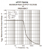
The datasheet for the lousy old 741 opamp shows its response when its gain is 10 should be -3dB at about 30kHz so its gain should be 10 from DC up to about 6kHz.
But you show a gain of less than 2 at 1Hz and less gain at higher frequencies.
AG, please read what the OP ACTUALLY wrote, it was VOLTAGE, not GAIN.
Also consider the numbers presented before launching off into a tirade about solderless breadboards, deficient signal generators and shonky old 741 op-amps.
JimB
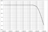
You have a table of output voltages at various frequencies.
You are looking for the gain of the amplifier, so you need to know the input voltage.
The gain is then the output volts divided by the input volts.
The gain can then be converted to dB using dB = 20Log10(V/v).
You do not state the input voltage so I am going to make the assumption that it was 200mV (0.2 volts).
Here is my interpretation of your results:
AG, please read what the OP ACTUALLY wrote, it was VOLTAGE, not GAIN.
Also consider the numbers presented before launching off into a tirade about solderless breadboards, deficient signal generators and shonky old 741 op-amps.
JimB
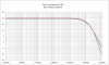
He wrote that the gain at 1Hz was 5.711146dB and his graph showed it. A voltage gain of 2 is 6dB so that is why I said his gain is less than 2.
His dB numbers dropped more at 3Hz, 10Hz and most higher frequencies.
His first schematic shows an input of 2Vp-p so the horribly slow slew rate of the lousy old 741 opamp reduced the frequency response much more. Most modern opamps produce frequencies above 100kHz at full output level with no problems.
Attachments
741 opamp poor slew rate limiting high frequencies.png
At the following frequencies I got 1.93V for 1Hz,3Hz,10Hz,30Hz,100Hz,300Hz,1kHz,10kHz. and for 30kHz i got 1.85V 1.33V for 100kHz ,300kHz i got 560mV 60mV for 1Mhz
This site uses cookies to help personalise content, tailor your experience and to keep you logged in if you register.
By continuing to use this site, you are consenting to our use of cookies.