Continue to Site

Welcome to our site!

Electro Tech is an online community (with over 170,000 members) who enjoy talking about and building electronic circuits, projects and gadgets. To participate you need to register. Registration is free. Click here to register now.

  • Welcome to our site! Electro Tech is an online community (with over 170,000 members) who enjoy talking about and building electronic circuits, projects and gadgets. To participate you need to register. Registration is free. Click here to register now.

Intermittent working PICs

Status
Not open for further replies.
Update . My previous post PK2 ZIF circuit works fine on 16F887 both PK2 standalone and MPLAB 8 operation ,( non LVP program / verify etc etc etc ) this is with external 5v power ON . the 887 has different LVP pins reason for extra option strap.

Edit... also now write...verify...etc 18F2420 ..:)

C....
Q what about PIC EE your circuit using it ...?
Q does your "running" PIC18F2431 circuit use RB5 PWM4 ... pin 26 by any chance ?

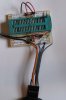
View attachment 91623

Hi G,

Well done, glad it's successful.

Here's mine.

PIC EE ????

No, RB5 not used.

Camerart
 

Attachments

  • ZIF circuit.jpg
    ZIF circuit.jpg
    469.7 KB · Views: 256
C If your program uses pic EEprom It would need to be initialized , similar but different to pic memory as previous posts, its default new chip state is usually FF . ( chicken and egg . needs to start at known value at least once )
 
hi C & Gran,
His programs do not use EEPROM, unless he has added to my original programs.
Eric
 
Thanks Eric, another mystery solved.

I tried changing the programs on a 'good' and a bad' PIC, then programmed the PICs again with the latest program, then READ them and compared the HEX files. Both the same. Again, I think they are programming ok.

Camerart.
 
Received 10x new 18F2431 PICs today (With a different batch number)

Same result as before. I now have 1x PIC that will erase, program a different program on it, erase, blank check, read, and re-program ok, works in the circuit. 5x other PICs from the first batch and 4x of the new batch don't work in the circuit, although they all Flash the LED as per the program.

I got onto Farnell technical support, tried an earthing wrist band, and grounding the circuit power before fitting PICs, still failed to get results. :banghead::banghead::banghead:

Camerart.
 
Once again, what is your target circuit? You showed us your ICSP circuit, but not the circuit you're putting the PIC in after programming it.

EDIT: Or do you have your ICSP and target circuit combined? Make sure you tell your PICkit to release the chip from reset after programming.
 
Same result as before. I now have 1x PIC that will erase, program a different program on it, erase, blank check, read, and re-program ok, works in the circuit. 5x other PICs from the first batch and 4x of the new batch don't work in the circuit, although they all Flash the LED as per the program.
Right! This confuses me...

1 works fine.... 4 of the new batch program fine... don't work in circuit, but do flash the LED...:confused:

Where is the LED?? Are you talking about the LED on the pickit 3???
 
Ian.. Camerart put a link to the project on post #21 [2] ... looks like a very long thread. He has sent me two nogo pics , just looking at them now... Can Oshonsoft produce / export an .asm file ?
 
Looking at the code!!! I assume Eric helped with this...

I also assume that you have turned off Define SIMULATION_WAITMS_VALUE = 1 ???

Just to be sure... I would hate it if this were causing your issues!!!
 
I only have the hex file from reading the two pics to work on the config is different by LVP bit . really need the QuadSim1.asm file ( think thats the name.)
 
hi,
These two images show the CONFIG used in all of the 18F2431 Oshonsoft Basic programs I have posted for the GPS scanner head demo/dev programs.
The project also uses a 18F4520, similarly CONFIG'ed.

E
 

Attachments

  • AAesp01.gif
    AAesp01.gif
    32.5 KB · Views: 251
  • AAesp02.gif
    AAesp02.gif
    39.4 KB · Views: 270
E + C I see the config STRVEN is disabled ...meaning Stack full / overflow does not cause a reset ? , was there a reason for this.... G
 
Hi,

Thanks all.

After many tests on these PICs I'm pretty sure that the problem is not theirs, but somewhere in the way I'm testing the circuit.

When I say circuit, I mean the motor drive circuit not the programming circuit, with Jumper for LVP and a LED for when voltage is present. This Pcircuit is working fine and I suspect the PICs are being programmed ok. In the Mcircuit there is also a LED.

EDIT: In the program there is a start-up LED flash, (Works on all PICs) then once AxxxExxx is received, the 'loop' starts and in the 'loop' there is a LED toggle, that tells me it is running. This toggle LED only runs on one PIC, and motors spin ok.

I am testing the Mcircuit by injecting the expected AxxxExx into the 18F2431, instead of how it should work, by an 18F4520 sending AxxxExxx to the 18F2431 (There will be 2x18F2431,s ignore) When I fit the programmed 18F2431 into the circuit, I must disconnect the AxxxExxx sending wire from the FTDI programmer, as it has voltage on it. I'm now looking at this as the most likely cause of the problem.

If I haven't answered all of the questions please ask again.

Eric has done nearly all of the programming. I only change anything with great reluctance. I had to change:
'Define CONFIG4L = 0x80 'LVP= 0 = Set for HVP
Define CONFIG4L = 0x84 'LVP= 1 = Set for LVP
Correct me if I'm wrong.

Camerart.
 
Last edited:
Morning C . Correct re LVP ... Your chips were one of each. But its probably not relevant at the moment , But STRVEN could cause a problem.
 
OK G,

I'm suspecting the voltages from the FTDI programmers that I'm using to inject the test signal into the 18F2431. This signal should come from the control PIC 18F4520. I'm going to try injecting test signals into this, hoping it will send the correct test data (AxxxExxx) into the 18F2431.

Camerart.
 
hi C,
Downloaded your [AAC] Conversation Basic Program.
Set Define to RUN in Oshonsoft IDE, also added BREAK and PORTA.2 [ manual input] to simulate a Match state.
Look at this image and add the two lines marked TEST ONLY [ don't forget Define SIMULATION_WAITMS_VALUE = 1]
Run the program, then using the hardware UART enter A123E090 for example into the UART Send window.
The program will Run to the BREAK, click PORTA.2 High on the PIC view image.
This will simulate a Match, then on the Sim Rate click Ultimate and the program will Run again.

Note the of the possible 32 STACK depth locations the Stack never goes over location 4, so the STRVEN is not a problem.
E
 

Attachments

  • AAesp01.gif
    AAesp01.gif
    52.2 KB · Views: 237
Status
Not open for further replies.

Latest threads

New Articles From Microcontroller Tips

Back
Top