Continue to Site

Welcome to our site!

Electro Tech is an online community (with over 170,000 members) who enjoy talking about and building electronic circuits, projects and gadgets. To participate you need to register. Registration is free. Click here to register now.

  • Welcome to our site! Electro Tech is an online community (with over 170,000 members) who enjoy talking about and building electronic circuits, projects and gadgets. To participate you need to register. Registration is free. Click here to register now.

Intermittent working PICs

Status
Not open for further replies.
:) Forget I typed ICSP , just serial programming ... , switch is required to power off while inserting / removing PIC .. (dont forget )

Please take note of atferrari post re setup memory.

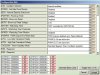
ED ...Just thought , LVP needs to be set in config bits also .?

ICSP, Ok,

I don't see LVP in config bits: attachment.

Camerart
 

Attachments

  • Clipboard01.jpg
    Clipboard01.jpg
    253.6 KB · Views: 230
Hola John,

My limited programming is in Basic, would you send the .BAS file please?

Your explanation is a bit difficult for me. I don't know what RTFM IIRC or SFR is. Or even TS.

If I suspect a programming problem, I use this routine: In PicKit2: Load program>program>erase>check for blank>re-program>verify. This mostly works, but obviously not always. Is this similar to what you are suggesting?

Camerart.

TS is "thread starter" (you).

SFR are the micro's special function registers.

RTFM means "read the fu***ng manual" /Edit to delete one "*" Edit/ :p :p :p

Even if you do not do Assembler, please ty to understand my routines:

The first, sets every register as it should be after a reset (as per the datasheet).

The second cleans or writes a value in every RAM position depending what you have set at compiling time (conditional compile).

Hope this is of help.
 
Last edited:
Just trying to cover all bases , its further down your config table.... You should be referring to the PIC datasheet more .

LVP is enabled by default . You probably need to search for a .bas clear / init routine.

are you using a laptop USB port ?


config.jpg
 
I wish I could be more help with the 18F2431 chip. Unfortunately, my experience is mostly limited to the mid-range and enhanced mid-range chips (e.g., 12F6xx and 16Fxxx or 16F1xxx chips). Whatever I say about the 18F chips is based on a brief comparison to the 16F series. My comment was generic, and as a note of interest, I was pointed in the right direction by the same Microchip forum that atferrari referenced.

You need to refer to the section in the datasheet that describes the memory organization. The Special Function Registers (SFR's) are described beginning around p. 65 through p. 69. I am sure you have used them, but may not have known them by that name.

The registers that specifically caused me problems are, using 16F nomenclature, the "Common Ram" and "General Purpose Ram." On the 18F, it appears Common Ram is still present (Bank0, 060h-05Fh; Bank1, 100h -1FFh; and Bank2, 200h - 2ffh). Note, those are 12-bit numbers and the first bit identifies the memory bank. The 18F has what is called "Access Ram" (000h-05Fh), which is 96 bytes. From my brief read, it appears those ram locations can be accessed from any bank in a single cycle and so might be considered analogous to the 16F "Common Ram" that can be accessed in a single cycle from any bank as well.

upload_2015-3-23_11-41-16.png


I was all set to post my Assembly program for clearing those registers, but after seeing atferrari's post, his code is probably more applicable to your situation. Our approaches were similar. I simply set up indirect accessing, cleared one register, incremented the file select register (FSRx), cleared the next register, and so forth.

In my case, the problem was created by using a Common Ram register for various flags. Those flags were not reset on re- programming and thus made the chip run erratically. For example, if an interrupt sets a flag for something and that flag is not cleared, your interrupt routine may see that "left-over" flag and not behave as you want it to behave. Of course, on the chips I am familiar with, clearing those RAM locations doesn't take long.

atferrari's routines also address the SFR's. He added a note of caution about erasing an SFR.

John
 
TS is "thread starter" (you).

SFR are the micro's special function registers.

RTFM means "read the fu***ng manual" /Edit to delete one "*" Edit/ :p :p :p

Even if you do not do Assembler, please ty to understand my routines:

The first, sets every register as it should be after a reset (as per the datasheet).

The second cleans or writes a value in every RAM position depending what you have set at compiling time (conditional compile).

Hope this is of help.

RTFM means "read the fu***ng manual" /Edit to delete one "*" Edit/ :p :p :p ............................Ah, now I understand:meh:
 
Just trying to cover all bases , its further down your config table.... You should be referring to the PIC datasheet more .

LVP is enabled by default . You probably need to search for a .bas clear / init routine.

are you using a laptop USB port ?


View attachment 91515

No matter how hard I try, I have to admit, I'm not good at this level of programming. Eric did most of the clever programming, and I'm very reluctant to 'play' with his settings, in case I mess up something I don't understand.

Once I've figured it out, I might change it though! In the last few posts there have been lots of things for me to to do correctly.

Yes, I'm using a laptop USB.
 
I wish I could be more help with the 18F2431 chip. Unfortunately, my experience is mostly limited to the mid-range and enhanced mid-range chips (e.g., 12F6xx and 16Fxxx or 16F1xxx chips). Whatever I say about the 18F chips is based on a brief comparison to the 16F series. My comment was generic, and as a note of interest, I was pointed in the right direction by the same Microchip forum that atferrari referenced.

You need to refer to the section in the datasheet that describes the memory organization. The Special Function Registers (SFR's) are described beginning around p. 65 through p. 69. I am sure you have used them, but may not have known them by that name.

The registers that specifically caused me problems are, using 16F nomenclature, the "Common Ram" and "General Purpose Ram." On the 18F, it appears Common Ram is still present (Bank0, 060h-05Fh; Bank1, 100h -1FFh; and Bank2, 200h - 2ffh). Note, those are 12-bit numbers and the first bit identifies the memory bank. The 18F has what is called "Access Ram" (000h-05Fh), which is 96 bytes. From my brief read, it appears those ram locations can be accessed from any bank in a single cycle and so might be considered analogous to the 16F "Common Ram" that can be accessed in a single cycle from any bank as well.

View attachment 91518

I was all set to post my Assembly program for clearing those registers, but after seeing atferrari's post, his code is probably more applicable to your situation. Our approaches were similar. I simply set up indirect accessing, cleared one register, incremented the file select register (FSRx), cleared the next register, and so forth.

In my case, the problem was created by using a Common Ram register for various flags. Those flags were not reset on re- programming and thus made the chip run erratically. For example, if an interrupt sets a flag for something and that flag is not cleared, your interrupt routine may see that "left-over" flag and not behave as you want it to behave. Of course, on the chips I am familiar with, clearing those RAM locations doesn't take long.

atferrari's routines also address the SFR's. He added a note of caution about erasing an SFR.

John

Could your routine be written in BASIC, this would give me a better idea.

Thanks for your information, I'm sure it relates to this PIC as well.
 
The only language I can write for PIC's is Assembly.

Can't you insert Assembly into an Oshonsoft program? I don't know how to do it, though.

John
 
Ah, now I understand:meh:

Hola again camerart

Do you have a way to narrow down the problem to see what register (or registers) is related to your problem? Otherwise you risk to spend lot of time chasing unexisting ghosts.

I presume that you could progressively "comment out" lines (or routines) until your difficulty eventually disappears. In fact, when creating software, doing the opposite, that is, adding progressively sections of code after the rest has been checked and accepted as OK, is the way to go.

If I mentioned the silicon errata, programming in no matter what language will not save you from the necessity to read it to see if your problem is coming from a flaw in the silicon. As you could check, depending of what batch each of your micros belong to, they could be differently affected (or not at all). Good thing to discard that and move on.

BTW, currently revisiting a project based on the eldest brother of yours, the 18F4431.

Buena suerte.
 
Last edited:
The only language I can write for PIC's is Assembly.

Can't you insert Assembly into an Oshonsoft program? I don't know how to do it, though.

John

hi John,
Its done as per this example.
Eric.

Code:
period:
ASM:  bsf STATUS,RP0
ASM:  movlw %11000110  'pu off,+RB0,tmr0 1:128
ASM:  movwf OPTION_REG
ASM:  bcf STATUS,RP0

loop0:
ASM:  movlw %00000100  '1:1,intclk, tmr1 stop
ASM:  movwf T1CON  't1 ext clock input via RC0
ASM:  clrf tmr1_cnt
ASM:  clrf TMR1L  'zero timer1
ASM:  clrf TMR1H
ASM:  bcf INTCON,1  'RB0 intr
ASM:  bcf PIR1,0  'clr tmr1 INTF
ASM:  bsf INTCON,3  'enb RB0 intr
 
I have a number of PICs, one works 'nearly' every time, and all of the others don't. I've tried 10s of times, changing them, re-programming, all with the same result.
Hi C,
If I recall correctly you have had problems programming other PIC types in the past, using that Prommer.??
Eric
 
What do you have your MCLR connected to while trying to run the program? If you leave it floating it will probably cause issues. It's usually best to have it connected through a diode and a resistor to V+ (holding it high to prevent undesired resets). Also put a 100nF capacitor between the MCLR pin and ground. Actually, it'd probably be better to do this:

Connect a 100-ohm resistor directly to the MCLR pin.
Connect a 100nF capacitor between the other side of the 100-ohm resistor and ground.
Connect a 10K resistor between the side of the 100-ohm resistor opposite the MCLR pin and V+.

Some people use a 1N4148 diode in series with the 10K resistor "pointing" down from V+ to the 10K resistor. This will prevent any oscillations from the power supply, but probably isn't necessary.

I still haven't seen a schematic for your current setup, so I don't know if you've done this already or not.

Regards,
Matt
 
Hola again camerart

Do you have a way to narrow down the problem to see what register (or registers) is related to your problem? Otherwise you risk to spend lot of time chasing unexisting ghosts.

I presume that you could progressively "comment out" lines (or routines) until your difficulty eventually disappears. In fact, when creating software, doing the opposite, that is, adding progressively sections of code after the rest has been checked and accepted as OK, is the way to go.

If I mentioned the silicon errata, programming in no matter what language will not save you from the necessity to read it to see if your problem is coming from a flaw in the silicon. As you could check, depending of what batch each of your micros belong to, they could be differently affected (or not at all). Good thing to discard that and move on.

BTW, currently revisiting a project based on the eldest brother of yours, the 18F4431.

Buena suerte.

Hi,
Using 1x 'good' and 1x 'bad' PICs. I tried different settings in the PicKit2 menus. Deleting programming, verifying etc, until I accidently erased the 'good' one. This re-programmed again OK. I noticed that if the 'code protect' or 'data protect' ticks are off, it will verify, but ticked it won't verify.

I am not able enough to comment out lines etc, for checking (I assume in the program?) and understand what's going on. I am pretty sure the problem is with the PicKit2 as suggested.

Camerart.
 
What do you have your MCLR connected to while trying to run the program? If you leave it floating it will probably cause issues. It's usually best to have it connected through a diode and a resistor to V+ (holding it high to prevent undesired resets). Also put a 100nF capacitor between the MCLR pin and ground. Actually, it'd probably be better to do this:

Connect a 100-ohm resistor directly to the MCLR pin.
Connect a 100nF capacitor between the other side of the 100-ohm resistor and ground.
Connect a 10K resistor between the side of the 100-ohm resistor opposite the MCLR pin and V+.

Some people use a 1N4148 diode in series with the 10K resistor "pointing" down from V+ to the 10K resistor. This will prevent any oscillations from the power supply, but probably isn't necessary.

I still haven't seen a schematic for your current setup, so I don't know if you've done this already or not.

Regards,
Matt

Hi,
I am going to follow the schematic on Post#36.

Camerart.
 
I noticed that if the 'code protect' or 'data protect' ticks are off, it will verify, but ticked it won't verify.

Hi , Don't play with data / code protect bits... You need to understand the workings LowVoltagePrograming bit settings ....do you ? check the datasheet , the circuit has option for both .

Were you using a laptop USB port for PK2 ?
lvp.jpg
 
Last edited:
Hi C,
If I recall correctly you have had problems programming other PIC types in the past, using that Prommer.??
Eric

Hi Eric,

Thanks for your code. I'm sure I'm missing something, but I simply added it into a program that works and got this error: See attachment.

Yes, I had problems before with this and a Velleman programmer. I suspect for similar reasons. 1/ I programmed the wrong type PIC, so that the config bits weren't correct. 2/This time, I suspect it was when I was editing the program with a TXT editor, and changed the page format or something similar, then when I opened it in Oshonsoft it spat it back out, then this problem was there.

Camerart.
 

Attachments

  • No compile.jpg
    No compile.jpg
    295.5 KB · Views: 232
View attachment 91511

OBVIOUSLY NOT FOR 3.3V PICs

Hi camerart. OK . the zif is a good idea , as stray connections need to be considered if doing ICSP . however you still need power caps and a pull-up during programming , ( I don't see them on your pic) also I would use external power during programming , as not all USB power is the same as your .5v ac measurement shows. (Is this a laptop USB port ?). WDT may be a wild goose , but worth checking .
Judging from your other project posts you seem pretty capable , I would suggest a course of action... put the zif on a stripboard with all the connections as detailed . add an external 5V supply plus a switch and led indicator .

Think john's post was referring to a routine to clear or initialize registers / data memory at start up (most important ).

Edit. I added a quick circuit of my ICSP setup as used with PK2 and PK3 with my PIC 16 /18 /24 dev bds . above specifically for the 18F2431


View attachment 91502View attachment 91503

Just getting ZIF socket ready for the suggested circuit. I wish I hadn't sealed it with hot glue, last time:arghh:

I also use it for programming 18F4520 PICs, will I still be able to?

Camerart.
 
Last edited:
Check your work with dmm without a pic in ZIF (even the best EE's make mistakes) , The circuit on #36 was specifically for picf2431, I had a look at 18F4520 below , I'm thinking you could add straps to cope with pinouts. not an ideal solution as it introduces opportunity for mistakes ,( I'm leaving you to sus it out ) keep in mind all the pic Vdd /Vss pins need a supply and a bypass 0.1 uF . and its not a good idea to supply I/O pins directly with Vdd .


Q are you understanding the various posts here regarding LVP ?

( Mistake ! Pin 1 is OK should have had green ink )

P4520.jpg
 
Status
Not open for further replies.

Latest threads

New Articles From Microcontroller Tips

Back
Top