Continue to Site

Welcome to our site!

Electro Tech is an online community (with over 170,000 members) who enjoy talking about and building electronic circuits, projects and gadgets. To participate you need to register. Registration is free. Click here to register now.

  • Welcome to our site! Electro Tech is an online community (with over 170,000 members) who enjoy talking about and building electronic circuits, projects and gadgets. To participate you need to register. Registration is free. Click here to register now.

InterCom / Door Phone

Status
Not open for further replies.
A cell phone (you call it a handphone) has a radio output power of up to 2W. When it is close to an unshielded electronic circuit then the circuit recifies the signal and produces high currents which can destroy it. A tiny piece of wire makes a good antenna at the microwaves frequencies from a cell phone.

Shielding a circuit from microwaves at 2W needs a certain education about the extremely high frequencies.
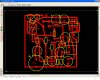
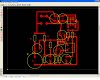
The circuit must be made on a pcb with a compact parts layout. A breadboard will cause all kinds of trouble.
The pcb must be installed in a metal case connected to 0V.
The mic must have shielded audio cable. Maybe the mic needs a shield around it.
The volume control must also be shielded.
The speakers might need to be shielded and use shielded audio cables.
 
but when i speak closer, the IC temperature also increased....

i going to start PCB work at next monday ....
the pcb necessary installed in metal case ? how about wooden case ?
i need to buy audio cable or 2wire shielded cable to connect the speaker with IC?

i not understand how to shielded the mic and volume controller .....
 
but when i speak closer, the IC temperature also increased....
Are you a dragon and you breathe fire?? Then cool down with some beer.

i going to start PCB work at next monday ....
the pcb necessary installed in metal case ? how about wooden case?
A wooden case will not block the powerful radio signal from the cell phone.
Maybe you can use aluminum foil as a shield inside the wooden case. Connect the foil to 0V.
i need to buy audio cable or 2wire shielded cable to connect the speaker with IC?
Maybe. Try the circuit with just a twisted pair of wires that might be a good enough shield.

i not understand how to shielded the mic and volume controller .....
Metal mesh woven with small spaces and covering the mic will pass audio but block radio waves when connected to 0V.
The wires feeding the volume control might need to be a shielded audio cable. Connect the metal case of the volume control to 0V.
Since the radio waves from a cell phone are tiny microwaves then the wires to 0V must be very short.
 
Last edited:
the aluminum foil need to fully cover the PCB?

the twisted pair of wires need to remove the covered plastic 1st before twist togather?

the volume control you mean is pin4 from IC?
 
the aluminum foil need to fully cover the PCB?

No, just completely surrounding it (line the box with aluminum foil).

the twisted pair of wires need to remove the covered plastic 1st before twist togather?

No, they should look like this:
**broken link removed**

the volume control you mean is pin4 from IC?

No, I believe he means the metal case of the potentiometer.

Sorry to jump in on your explanations, AG. Is this what you meant?
 
Last edited:
that not just the meaning?

You do not want to literally cover the PCB with aluminum foil directly. That will probably cause shorts that could damage your components. You do want it to be completely surrounded by sheets of foil, but not touching them.
 
Cover the inside of the wooden box with aluminum foil. Also cover where wires enter the box and leave. Connect the foil to 0V with a very short wire then it will be a very good shield to radio waves.

DO NOT connect the shield to pin 4 of the IC that is the volume control pin.

Aren't you using the volume control shown on the schematic of the intercom? It does not use the pin 4 volume control on the TDA7052A because it was designed for the TDA7052 that never had an internal volume control.
 
mean the foil no need seal off the PCB or box ?

The foil needs to be completely lining the inside (or outside) or the box, but cannot be touching the PCB. Does this make sense?
 
ya... i completely lining the inside the box and seal off the PCB not just the same ? it wont touching the PCB
 
Last edited:
ya... i completely lining the inside the box and seal off the PCB not just the same ? it wont touching the PCB

Okay, then that should work just fine.
 
The pcb should be mounted in the center of the wooden box that is lined with aluminum foil. The foil is connected with a short wire to 0V so it is a shield. Do not let any conductor on the pcb to touch the foil.
 
0V on the circuit board is the ground common connection for the entire circuit. You want all shields to connect to it. The 0V from the battery is also connected to the 0V on the circuit board.
 
Why do we have 4 months (about 122 days) and 156 posts about this extremely simple circuit??
 
here is my PCB design , and the DTDP switch connection correct or not ?

once i trying the circuit , the circuit not function and the temperature of TDA7052 in master circuit continue increasing .....
 

Attachments

  • C1.JPG
    C1.JPG
    188.6 KB · Views: 244
  • C2.JPG
    C2.JPG
    165.4 KB · Views: 250
here is my PCB design , and the DTDP switch connection correct or not ?

once i trying the circuit , the circuit not function and the temperature of TDA7052 in master circuit continue increasing .....

This is a typical example of "How not to design a PCB".

You're using the wrong layer for the traces. Using the bottom layer (16) for traces and the tPlace layer (21) for components you'll obtain a "look through the board" image. Using the top layer for traces you'll have to solder components from the component side, which is impossible since the solder pads will be obstructed by the part itself.

Using a double sided board with plated through holes the board is easier to populate and solder.

Further there are lots of acute and odd angles in the traces which will most likely lead to unsatisfactory etching results.

Last not least there are components overlapping each other from their size. How are you going to place those properly?

Why didn't you refer to my PCB design? I guess the PCBs are also smaller than yours.


Boncuk
 
Last edited:
Status
Not open for further replies.

Latest threads

Back
Top