Continue to Site

Welcome to our site!

Electro Tech is an online community (with over 170,000 members) who enjoy talking about and building electronic circuits, projects and gadgets. To participate you need to register. Registration is free. Click here to register now.

  • Welcome to our site! Electro Tech is an online community (with over 170,000 members) who enjoy talking about and building electronic circuits, projects and gadgets. To participate you need to register. Registration is free. Click here to register now.

InterCom / Door Phone

Status
Not open for further replies.
You wrongly connected the emitters of the transistors together! Why?
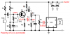
Look at the original circuit from RED Circuits where the collectors are connected together and the grounds are connected together.
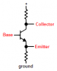
Maybe you don't know which pin is the collector or emitter on a schematic so I labelled them here.

The sound from the master's mic is fed through its transistor to the amplifier in the slave where it is attenuated a little with R10 and R11 then amplified so it will be fairly loud.
(The original circuit used the TDA7052 (39dB gain) which has more gain than the TDA7052A (35.5dB gain). Also the TDA7052 has an input impedance of 100k but is only 20k for the TDA7052A so the attenuation by R10 and R11 in Boncuk's circuit is more than with the TDA7052.)

The sound from the slave's mic is fed through its transistor to the amplifier in the master where it is attenuated a little the amplified so it will be fairly loud.

You are supposed to adjust trimpot R7 so that no sound from the Master's mic comes out of its speaker and you are supposed to adjust trimpot R7A so that no sound from the slave's mic comes out of its speaker.
 

Attachments

  • transistor2.PNG
    transistor2.PNG
    3.5 KB · Views: 208
because i would like to try this circuit Transistor intercom circuit. - Electronic Circuits-Circuit Diagram-Electronics Projects-Design , if the preview intercom wasn't work ....

this circuit got "discordance" after i connected speaker , but the preview intercom show silent at all the time.....

That BEL187 you can replace with AC187 and will give you better power output than any silicon type alternatives considering the simplicity of the circuit. But package is different. Later one is expensive to get.
 
ok .... i will try using TDA7052 and adjust the R7 ... hope the circuit will work well....

the speaker1 can fairly loud ... just dunno why the speaker2 can't function well... the voiced was not clearly enough, and having howling....
 
Last edited:
Since your circuit is silent all the time then you have something connected wrong. The difference between the TDA7052 and TDA7052A will be small. You did not say if you connected their grounds together.
Your DC voltages before were completely wrong but are good now. What changed?
 
my DC voltage were completely wrong, what's my mistake ? now, i just using 1 DC generator to connecting both +12v DC and Gnd togather....

and i added 0.47uF capacitor as you listed before, after that the circuit didn't shorted after i connected speaker, and also can transfer voice now....
 
Last edited:
You're connecting both +12VDC and Ground TOGETHER?????
 
It looks like the input coupling capacitor that is shown on the datasheet of the TDA7052A is important but is not needed for the original TDA7052.
I wonder why the intercom doesn't work?
 
TDA7052 and TDA7052A have basically the same pin layout.

While pin4 of the TDA7052A is a DC volume control pin it is unconnected in the TDA7052 chip.

I already pointed out not to have been aware of the difference since the data sheet offered for download was the one of the TDA7052A.

Anyway, using the TDA7052 instead of the 7052A will lead to the desired results with the PCB layout unchanged - except for correcting C4 orientation on both boards.

Also there is absolutely no reason why to mess with two voltage sources: When using two separate supply voltages you must connect circuit grounds together!

Y1-1 connects to Y1-1A, Y1-2 connects to Y1-2a, Y1-3 connects to Y1-3A and Y1-4 connects to Y1-4A.

Y1-1 = +12V, Y1-2 audio signal in/out, Y1-3 shield, Y1-4 circuit ground.

Boncuk
 
Last edited:
Anyway, using the TDA7052 instead of the 7052A will lead to the desired results with the PCB layout unchanged
Then why did Non89 say that the output voltages of the TDA7052A were corrected when he installed the recommended input coupling capacitor?

I think when the DC volume control was added on the TDA7052A then its input bias voltage became higher than 0V requiring the input coupling capacitor shown on its datasheet.
 
I think Non89 has not made any PCBs for the intercom yet and is still testing using trial and error.

Also, with two identical circuits close together I can imagine that there is acoustic feedback, explaining the noise he complained about.

If he had used my PCB design pin4 had no effect since it is left unconnected.

Boncuk
 
Boncuk, does the author replied you ?

although i m just testing on board, but should be no different if connected correctly...
 
Last edited:
I was tested , TDA7052a need o.47uF capacitor as listed before , but TDA7052 no need....

the C4 have no polarity problem on the original circuit, if i m using TDA7052.....

By using TDA7052, when i changed to C4 positive polarity connected to Q1,the voltage became unstable(increased or decreased uncertainly, caused short circuit frequncely), when connected C4 negative polarity toward Q1, the voltage is stable and circuit work well......

the only problem i facing now is - No matter how i adjusting the R7( i m using trimpot 30K on all variable resistor) , i also cant stop the voice out from both side ( the best i can do is speak in mike2 = speaker1 voiced , speak in mike1 = both speaker voiced)........
 
Last edited:
Look for flaws on the board carrying mike1.

Another suggestion: Keep the circuits at least 2 yards apart.

Yes, the author has replied which I already reported here. He is going to publish a revised schematic (as soon as he has enough time to do so.)

Boncuk
 
By using TDA7052

C4 positive connected to Q1 : mike1 speak = speaker2 voiced , mike2 speak = speaker1 voiced( but very quietly) , main problem is the voltage always charge and decharge, causing the circuit shorted in few second, function at few second... repeat and repeat recycling .....

C4 negative connected to Q1 : mike1 speak = speaker2 voiced , mike2 speak = speaker1 voiced(still not loudly enough) , (and i experience once before , once the circuit working long duration, master circuit speaker1A became +10V, speaker1B became +1.xV , and all the sound from both mike voiced out from speaker 2 only....the speaker1 temperature is HIGH)
 
Last edited:
the C4 have no polarity problem on the original circuit, if i m using TDA7052.....

By using TDA7052, when i changed to C4 positive polarity connected to Q1,the voltage became unstable(increased or decreased uncertainly, caused short circuit frequncely), when connected C4 negative polarity toward Q1, the voltage is stable and circuit work well......
Look at the voltages on C4. The emitter of the transistor is at a positive voltage of about +5.4V and R8 causes the other end of C4 to be 0V. The original circuit had its polarity backwards. If you had yours connected backwards then maybe it was destroyed so replace it and connect its polarity correctly.

the only problem i facing now is - No matter how i adjusting the R7( i m using trimpot 30K on all variable resistor) , i also cant stop the voice out from both side ( the best i can do is speak in mike2 = speaker1 voiced , speak in mike1 = both speaker voiced)........
Then you have the transistor or R7 connected wrong. The collector signal is 180 degrees from the emitter signal. When you adjust R7 then the two signals cancel and there will be no sound from the local speaker. That is how the circuit avoids acoustical feedback howling.
 

Attachments

  • intercom.PNG
    intercom.PNG
    8.6 KB · Views: 229
just connected as shown.... the R7 just need to adjust once or everytime when speaking??
 

Attachments

  • rt10k_pl.jpg
    rt10k_pl.jpg
    20.5 KB · Views: 214
just connected as shown.... the R7 just need to adjust once or everytime when speaking??

You should only need to adjust it once to get it to the proper setting.
 
When i open my Handphone tune closer to the mike ( to get more loudly voice out) , the IC temperator start increasing.... just in few sec , the IC was spoiled .... how come this happening ?
 
Status
Not open for further replies.

Latest threads

Back
Top