Electro Tech is an online community (with over 170,000 members) who enjoy talking about and building electronic circuits, projects and gadgets. To participate you need to register. Registration is free. Click here to register now.
Welcome to our site! Electro Tech is an online community (with over 170,000 members) who enjoy talking about and building electronic circuits, projects and gadgets. To participate you need to register. Registration is free. Click here to register now.
I guess the device connected doesn't care for the color of the insulation.
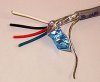
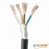
Normallly red is used for +UB (+12V), black is used for circuit ground and any other color is used for the AF signal. The shield is wire mesh around the entire bundle of cables.
Once again, use 4 wire shielded cable between master and slave.
Do you really think that the colour of a wire affects the sound?
One wire is the signal wire that is surrounded by a shield. But the cable you showed has no shield.
Do you really think that the colour of a wire affects the sound?
One wire is the signal wire that is surrounded by a shield. But the cable you showed has no shield.
Do you really think that the colour of a wire affects the sound?
One wire is the signal wire that is surrounded by a shield. But the cable you showed has no shield.
You showed a cable with RCA connectors. They are usually shielded. If they are used for speakers then they are not shielded.
Simply cut off an RCA plug and look at the cable. If it is shielded then you will see a signal wire that is surrounded by the shield.
A DPDT switch is Double Pole Double Throw. It has two (double) separate switches called Poles. Its toggle contact goes in two (double)Throws (directions). It has 6 contacts, 3 for each switch.
When the DPDT is in one direction then the mic signal is shorted by one of its switches and the other switch turns on the "silent" LED. when the switch is in the other direction then the mic is allowed to work by one of its switches and the other switch turns on the "speak" LED.
When I use a switch to short a low-power signal then I use a switch that has gold contacts. Gold doesn't corrode like high current silver switch contacts. It costs the same.
It's purpose is to adjust speaker volume for the master unit. The slave unit has a fixed volume setting through the voltage divider consisting of R10 (4.7KΩ) and R11 (10KΩ).
If that volume setting is too low increase the value of R11 to 12 .. 15KΩ. If it's too high increase the value of R10 to to 6.8 .. 8.2KΩ leaving R11 unchanged.
S1 (A and B) is the "privacy" switch. It should be a latching switch and needs to be operated if somebody rings the door bell and you want to talk to the person. Part A of the switch prevents AF to go through the amplifier and part B switches LEDs for visual control of the switch setting "SILENT/SPEAK".
Without that switch all communication from inside the house will be heard at the door.
If you don't need the switch omit it completely as well as R9 and and D1/D2. Make a wire jump from switch terminals 1 to 3.
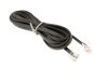
the cable is not shielded! It's twisted pair cable used for telephones. Check the attached image of a four wire shielded cable. You don't need a cable with a drain wire (blank copper wire within the insulation), but you need either copper mesh or any metal foil for shielding.
The switch doesn't have double pin names. There are two electrically isolated switches in the enclosure being activated simultaneously.
A DPDT-switch is a double pole double throw switch.
Pin numbers in my schematic are 1 through 6. Switch part A has pins 1 through 3 and part B has 4 through 6.
Pin assignments for functions are pin1 (4), pin 2 (5) and pin 3 (6).
Take a good look at the PCB design. The switch functions are clearly visible.
No.
Each R7 is adjusted for a null of your voice in your speaker to prevent acoustical feedback. Then the circuit will operate in full duplex without using press-to-talk switching. Both people can talk to each other at the same time without switching.
The two P1 pots are volume controls and maybe should be hidden trimpots so they are not turned down to zero.
here are the circuits you 1st and 2nd time you sent for me , i want to ask why got 2 more extra connection , that mean i need shielded 6-wire cable ....?
You can do what I did and make a really simple intercom using an LM386, 2 mics, 2 speakers, and a relay. It was really simple to make, and I used it with my door lock. It is cheap and simple, but the sound quality is rather low but that is to be expected.
You can do what I did and make a really simple intercom using an LM386, 2 mics, 2 speakers, and a relay. It was really simple to make, and I used it with my door lock. It is cheap and simple, but the sound quality is rather low but that is to be expected.
because i need to pass up this circuit , if i choose simple intercom , my lecturer sure asking me add more circuit , etc output to door bell or any else ....
This site uses cookies to help personalise content, tailor your experience and to keep you logged in if you register.
By continuing to use this site, you are consenting to our use of cookies.

")