Electro Tech is an online community (with over 170,000 members) who enjoy talking about and building electronic circuits, projects and gadgets. To participate you need to register. Registration is free. Click here to register now.
Welcome to our site! Electro Tech is an online community (with over 170,000 members) who enjoy talking about and building electronic circuits, projects and gadgets. To participate you need to register. Registration is free. Click here to register now.
i want to make a intercom / doorphone , anymore application i can added with intercom/ doorphone?? i was found some circuit design , but i hope anyone else can show me more, thank you ~
Most simple cheap intercoms are half-duplex. That means they transmit sounds only in one direction at a time. A pushbutton is used inside for push-to-talk and release to listen. Voices frequently get cut off.
Better more expensive intercoms use an electronic voice switch that transmitts when there is sound at the microphone but frequently voices get cut off. Background sounds keep it transmitting in one direction.
A better intercom is full duplex. It cancels local feedback but both ends can talk and listen at the same time. Here is a full-duplex intercom circuit from www.redcircuits.com :
my lecturer said i need to add 1 or few more application in the intercom , but intercom like a unaided circuit... if i combine with doorbell ... its feel strange also
The "slave" has no option to adjust volume (Playing kids could turn it all the way down and the caller returns home frustrated.)
The "master" has a private button switching off the mic if there is no need to talk. (Nobody is supposed to listen to the private dialogs in the house.)
To combine the intercom with a doorbell do the usual thing and add a doorbell pushbutton.
Here are the detailed schematic and PCB designs.
When interested PM me your email address for the Eagle files.
I really don't understand the problems you are having.
Just connect the 4-pin wafers as shown in the schematic and also on the PCB layout with the same pin numbers on both boards.
There are four pins to connect which are: +12V, circuit ground (negative terminal of the power source), AF-signal and shield for the AF-signal.
Connector numbers are Y1 for the master and Y1A for the slave. Pins1 on each connect to +12V, pins2 connect the AF-signal, pin3 and 4 connect to ground and ground shield.
I drew in the AF-signal in red and the shield in blue. Check the pin numbers. They are identical - master has the identifier Y1 and the slave has the identifier Y1A. Pin numbers have to be connected to the same pin numbers on both wafers. 1-1, 2-2 etc.
The cable used to connect the intercoms together is shielded audio cable. Some countries call it "screened" cable.
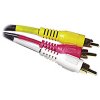
In North America audio components are connected together with audio shielded cables that have an RCA plug on each end. Just cut off the plugs. The cable has a center conductor that is used for the signal and it is insulated then is surrounded by the shield which is connected to the circuit ground at each intercom station.
An audio generator is used if you want to communicate in Morse Code (...---...) send-over-sandwiches.
An audio generator is also used to test and measure the circuit's max output level, frequency response and distortion.
Some smokers got throat cancer and had their voice box removed. They hold an audio generator (square-wave buzzer) to the hole in their throat to speak.
A door intercom has a Master that is indoors and the Slave is outdoors. The person at the slave rings a bell then the person at the master can talk to the person at the slave.
People don't talk with a signal generator. A pc has nothing to do with it.
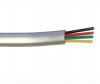
You show a simple cable with 4 ordinary wires. It is used for a telephone, door bell or a furnace thermostat. Since it is not shielded audio cable then it will pick up mains hum and other interference.
The intercom circuit must be connected with a shielded audio cable that has one signal wire that is surrounded by a shield.
I don't know why Bonkuk's schematic has so many connections (maybe to feed power from the mater to the slave) but his signal wire is thick red and the shield is blue.
Connecting pin1 of the master with pin 4 of the slave you'll have a dead short in your power supply making it smelly very quickly. Also connecting the "hot" AF-side to ground will result in no sound.
All wires have to be connected according to pin numbers (1 by 1).
To audioguru:
The OP wanted to connect the intercom to his PC sound card, which made two more two-pin connectors necessary.
The slave board would be sufficiently fitted with a three-pin connector, but I decided to use a 4 pin connector for equal pin count on two boards and to have circuit ground and shield separated. A four-pin connector guarantees no significant current flow on the shield.
you mean this kind of cable?? normally how many wire inside? based on boncuk cable diagram , he only using 2 wires inside which is AF and ground only .... i think the +12V can use a normal wire ....
The RCA cables you show have a signal wire surrounded with a shield. One is perfect for the signal and shield from the Master intercom to the Slave intercom. Ordinary wires can be used for the power supply wires.
This site uses cookies to help personalise content, tailor your experience and to keep you logged in if you register.
By continuing to use this site, you are consenting to our use of cookies.