Continue to Site

Welcome to our site!

Electro Tech is an online community (with over 170,000 members) who enjoy talking about and building electronic circuits, projects and gadgets. To participate you need to register. Registration is free. Click here to register now.

  • Welcome to our site! Electro Tech is an online community (with over 170,000 members) who enjoy talking about and building electronic circuits, projects and gadgets. To participate you need to register. Registration is free. Click here to register now.

installing headphone jack - background noise now. pls help

Status
Not open for further replies.

k9sar

New Member
I have done this mod multiple times in older tv sets but this time I seem to have done something wrong.

background: I purchased a LCD TV for my son at school and it does not have a headphone jack or audio out (RCA etc). He will use it for TV, XBOX and Computer (second monitor) and I would like for him to be able to use a set of headphones that he currently has (turtle beach gaming headphones) so he does not disturb his roommate. Controlling mute and volume from the TV is a must since his headphones only limit the volume (they do not have built-in amps).

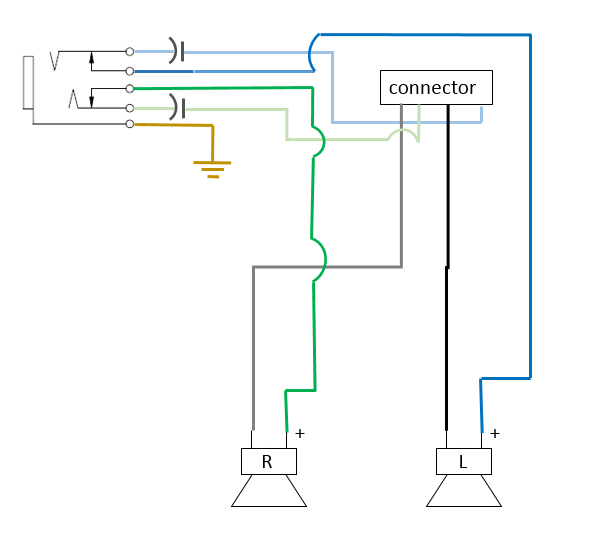
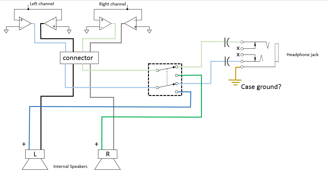
I installed a 3 conductor (stereo) closed circuit 1/8" headphone jack by interrupting the (+) for each speaker and routing through the jack. I tied the (-) wires to the common ground for the jack though I think this may be where I went wrong. The headphones have separate L and R (+) but a common (-) while it looks like the tv speakers may not share a common (-). I have not tried to trace the circuit on the internal board to verify this.
Long story short, the speaker interruption and volume control work fine (it seems) but there is static on the line which does not seem to be volume controlled and is audible in the speakers during normal operation and through the headphones when plugged in.

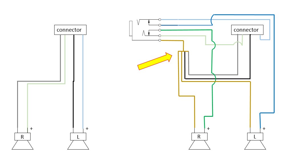
I have attached a picture of the wiring, original and modified (forgive the rough sketching. I'm not an artist). The yellow arrow points to where I think the problem is. I would appreciate feedback as to what the issue could be and how to resolve it. I don't have the specs on the headphones but the internal TV speakers are little 12ohm 5w ones.
wiring-vi.png

also, I want to keep the cost down. IF the needed 'parts' cost too much, I'll probably ditch the TV and buy a more expensive one that has the needed jack(s) if I can find one. :)
 
Last edited:
Likely it had bridged +- outputs like a car stereo , and when you connected the gray and black wires together, you shorted two of the amplifiers to each other. You will need to add two audio transformers..., or find the real ground, and go single-ended through a DC blocking capacitor to the right and left channels...

'7ark
 
Ok, you have just exceeded my garage-electronic capacity. So is what you are saying is that I should leave the black and grey connected as original and take the common brown from the jack to a 'real' ground? I can probably crawl around online and figure out what size capacitor(s) to use but where would they fall within the picture? I'm almost embarrassed by asking these questions that may seem simple to you folks here on the forums.:sorry:
 
Picture: (showing only one of two channels)

audio.gif


73
 
so, if I think of this correctly, I would replace the black and gray wires to their original state. These would be represented by the line from U2 to (-) speaker in the first diagram assuming that the bridging (U1, U2 etc) is on the circuitboard before the connector allows me access. I would leave the interrupted blue (and green) the way they are routed to the jack with the exception of the addition of a capacitor on each line. This leaves the brown common (-) for the headphones themselves. I would ignore any connection to the existing speaker wiring and connect that directly to a ground point (? more of a question than a statement) like the case itself.

wiring2-vi.png

Won't that affect the normal speakers when there is no headphone inserted? Not sure if it matters or not. If it matters, I guess I could throw a DPDT switch in there to interrupt/redirect the blue and green wires and not have anything returning from the headphone jack.
 
When you insert the external plug, the jack switch contacts have to break the connection to just one side of the internal speakers. It might take a bit of effort to find a jack that does that, but I know they exist.
 
I believe that to be what I have. Looking at the pic above, the left channel + would normally run from the connector (light blue wire), through the capacitor, through the jack via closed circuit with dk blue wire and to the speaker. When the headphone plug is inserted, the lt. blue to dk. blue connection is interrupted and the lt.blue heads out to the + left channel in the headphones. Similar to the green. It's the "through the capacitor" during normal operation that has me questioning.

ps. thanks for your patience and information
 
I wasn't sure if your diagram is for the external speakers, or the internal ones. You do not want to have the capacitor in-line when using the internal speakers.
 
yes, the speakers indicated are the internals. Any external audio would be through the 1/8" plug I am installing.. you know, the pain in the butt one with the common ground that doesn't quite work like I would like. :) It looks like I can install a DPDT switch that will take the (+) for each internal speaker channel and either connect to the appropriate internal speaker or to a headphone jack that need not be interrupting (closed circuit) through a capacitor. Now I think I may be confusing things even more. If I am not using the internal speaker (-) wires and not doing a loopback when there is no headphone inserted, what's the point of the capacitors again?
 
If operating a speaker from two bridged push-pull audio amps, then no capacitor is needed or wanted because there is no DC component across the voice coil. If operating a speaker from a single audio amp, then a DC blocking capacitor is needed otherwise the DC component across the voice coil will damage it or the amp...
 
ok, in summary... don't cross the streams. I think I have it now. here's a new pic. I can use an open loop headphone jack (no loopback) or just use my existing and don't connect the contacts back to the internal speakers. I'll use a DPDT switch to select between internal speakers and headphones (he can leave the headphones plugged in at this point too since they have no effect on the internal speakers)

wiring3-vi.png


I'm still looking into the needed size for the capacitors... I see a lot of suggestions of 220uf in audio applications but without actually knowing my DC voltage, I can't be positive.
Final questions:
Should the ground on the headphone jack be just a ground to the case or should I try to chase the board to find where the amps ground (if it's electrically different)?
Is there any way to take a measurement or something to verify that I do indeed have bridged amps?
 
ok, in summary... don't cross the streams. I think I have it now. here's a new pic. I can use an open loop headphone jack (no loopback) or just use my existing and don't connect the contacts back to the internal speakers. I'll use a DPDT switch to select between internal speakers and headphones (he can leave the headphones plugged in at this point too since they have no effect on the internal speakers)
Your diagram looks ok now...

I'm still looking into the needed size for the capacitors... I see a lot of suggestions of 220uf in audio applications but without actually knowing my DC voltage, I can't be positive.
Several hundred uF, >15Vdc

Should the ground on the headphone jack be just a ground to the case or should I try to chase the board to find where the amps ground (if it's electrically different)?
I would trace back the internal speaker connector, and look to see what the audio comes from. If you look up the audio amp chips, the pin out would tell you where the ground is.

Is there any way to take a measurement or something to verify that I do indeed have bridged amps?
A scope. But you would have to find the ground you need ahead of using it. Make sure that the TV doesn't have a "transformerless power supply" where the internal chassis is connected to 120Vac if the plug is inserted upside down.
If bridged, the voltage at the two ends of the internal speakers would both have equal amplitude signals, but opposite phase, as measured from the amplifier's ground.
 
Status
Not open for further replies.

Latest threads

New Articles From Microcontroller Tips

Back
Top