Continue to Site

Welcome to our site!

Electro Tech is an online community (with over 170,000 members) who enjoy talking about and building electronic circuits, projects and gadgets. To participate you need to register. Registration is free. Click here to register now.

  • Welcome to our site! Electro Tech is an online community (with over 170,000 members) who enjoy talking about and building electronic circuits, projects and gadgets. To participate you need to register. Registration is free. Click here to register now.

Insrument Panel Illumination

Status
Not open for further replies.

Tim2

New Member
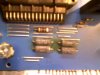
Hi To All, It's good to see a site like this. I browsed through the topics a little and didn't see anything on IP PCBs. I'm trying to repair the board on a 1988 Buick Regal. The Fuel Gauge and Warning Lights work, but that's about all. I've got four resistors that I suspect to be the problem, but can't find any info online for the wire-wound radial resistors. If anyone knows of a site which has values for replacement resistors of this type or has in-sight into what I'm dealing with would be greatly appreciated. The only info I have on the old resistors are:

Dale
CW-2C-1
150 ohm
5% (tolerance)
100PPM

and

2 different numbers on 2 of the 4 resistors are:

8823 (on one)
8821 (on another)

What I don't know is the wattage. I'm guessing .5w, but searching the numbers all I can find is 3 watt and up. I understand that I don't want to go undersize, but are there any foreseeable problems on an OLD OLD car with going over size or damaging the other IP components thereby?
Thanks for building and maintaining this site!
 

Attachments

  • PIC-1597.jpg
    PIC-1597.jpg
    30.8 KB · Views: 337
8823 means the resistor was made in the 23rd week of 1988, similarly the other was made in the 21st week.
 
Why do you 'suspect' the resistors, I would imagine they are VERY, VERY unlikely to be the problem - such resistors are extremely reliable.

Easy to test them, just stick a multimeter on ohms across them and see what they read - although this could vary depending on how they are connected (and it looks like they may be in series/parallel).
 
OK. Thanks Mike. I couldn't figure why the same specs would have conflicting #'s like that. Wish I could find the original power rating on those resistors. Digi-key & even Vishay-Dale don't list it anymore.
 
Hi Nigel. The circuit board has gotten vary hot there and the resistors have changed color.
 
Why do you 'suspect' the resistors, I would imagine they are VERY, VERY unlikely to be the problem - such resistors are extremely reliable.

Easy to test them, just stick a multimeter on ohms across them and see what they read - although this could vary depending on how they are connected (and it looks like they may be in series/parallel).

Sorry, I missed this. I tested earlier today, but forgot the reading, but they were somewhat less than 150 ohms, yet consistent with one another. Then I figured since they were still mounted on the board, I wasn't going to get a reading that helped me anyway. I'll put the meter back on and report back in a few.
 
All 4 measure 37.3 Ohms. 2 are in series and 2 are parallel.

That sounds perfectly reasonable, if you really wanted to test them, simply disconnect one end of each resistor and test them individually - but I certainly wouldn't bother, and I wouldn't have been looking at those possibly been faulty in the first place.

If they had been overheated, and failed, it would be blindingly obvious, and you'd have a hole burnt through the board.

I've presuming those resistors feed the illumination?, and also that the illumination is adjustable? - FAR, FAR more likely that the fault is the electronics for the adjustment, or most likely failure of the bulbs.
 
Thanks Nigel. These might have been old in 1988 and are ancient in 2013, but I find it confusing that the standards didn't support exact identification of power rating. At least it doesn't help me cross-reference.
 
I've had the light switch in mind with the built in dimmer as a possible suspect. I'm beginning to think I've got 2 issues to solve; one being the vehicle speed sensor also - for the dead speedometer and odometer. I just wanted to satisfy my mind before I reinstalled the panel and moved to other areas. The bulbs are all good.
 
I meant "very", not "vary". I don't like to go slack in the grammar department; that could lead to total failure. hehe
 
Thanks Nigel. These might have been old in 1988 and are ancient in 2013, but I find it confusing that the standards didn't support exact identification of power rating. At least it doesn't help me cross-reference.

Simple observation tells you the power rating, they are standard 2.5W resistors - here's a scan of a couple I've just taken out of a draw :D
Resistors.png
 
I think you're right, Nigel. Everything controlled by the dimmer circuit is inoperable. The speedometer and odometer get pulses from the speed sensor. The burnt out segments on the speedometer are related to the LED board.
 
FWIW, I had a 1990 Buick Regal that developed instrument panel problems. I assume it was somewhat similar to the '88 version. The Buick solution was, of course, to buy a new panel. I opened it up like Tim2 has done. Hot resistors may not be bad. They may be intended to run that way. On looking around and wiggling, I found a couple of cold solder joints, one of which had failed completely. Re-soldering was all that was needed.

John
 
Thanks for your input, John. I've probably allowed myself to be thrown off course here. A lot of sites give instructions on the newer GMs panels which have weak solder joints with surface mount resistors falling off. They're replacing them with through hole components.
 
Status
Not open for further replies.

Latest threads

New Articles From Microcontroller Tips

Back
Top