Continue to Site

Welcome to our site!

Electro Tech is an online community (with over 170,000 members) who enjoy talking about and building electronic circuits, projects and gadgets. To participate you need to register. Registration is free. Click here to register now.

  • Welcome to our site! Electro Tech is an online community (with over 170,000 members) who enjoy talking about and building electronic circuits, projects and gadgets. To participate you need to register. Registration is free. Click here to register now.

Input For PIC uC

Status
Not open for further replies.

mesamune80

New Member
Hi all,

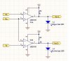
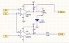
i am using a comparator ic and LM393 ,configured it as windows detector circuit with the output go to LED and pic uC pin.
But i could not read any high logic from the ic output pin when the pin is goes high. i am using a 1k pull up resistor for the power (12v) to LED which is parallel to uC pin as well which i want the uC to detect it is logic high.
Any problem with my configuration?
 
Remove the comparator part from the uC & check the comparator whether it is working correctly?

Can you see the LED goes on when input logic = 1 (in between your range)?

What input did you feed the input?Inverting pin or for the non inverting pin?

Note that its output open collector type.
 
Last edited:
ya,my LED lit but i could not get any signal to my uC pin.
my circuit is look like this with the VrefA and VrefB to my pic uC pin (input pin)
Is there anything i need to add so that my uC can detect logic 1 and 0 respectively?
 

Attachments

  • Windows Detector1.jpeg
    Windows Detector1.jpeg
    21.4 KB · Views: 216
i see ,thanks nigel ,but i need some indication for that? (high and low limit indication)
can i do it in a different way? or any alternative for that?
 
Use a transistor to feed the LED.

Or, more crudely, put a resistor in series with the LED - but this will still restrict the output of the comparator from going fully high, and reduce the LED's brightness.
 
Nigel Goodwin said:
Use a transistor to feed the LED.

Or, more crudely, put a resistor in series with the LED - but this will still restrict the output of the comparator from going fully high, and reduce the LED's brightness.

Hi Nigel,
Just noticed he is using a +12V supply to the LM393...:eek:
 
It seem like i got not much choices,either a transistor or a dim LED =_="
what transistor is suitable for this i can use 2N222?
 
mesamune80 said:
okay i'll try it out ,thanks guys.
hi,
You could do it this way.

I have modified the top LED, I'm assuming a Red LED about Vfwd=2V

The LM393 is open collector output, also the PIC analog is a high impedance.
 
Last edited:
Thanks for all the replies,really thanks for all of you.
i think i might choose either zener or voltage divider method to power up both my LED and also signal to my uC. =)
 
Can i put it this way? so that i can adjust untill the voltage to my uC is about 5V at the same time i also can light on my LED.
Or any better idea i can use? at the moment i have 10k adj resistor and 1k resisitor.
 

Attachments

  • sample.JPG
    sample.JPG
    22.4 KB · Views: 169
Last edited:
i had thried the above mothod which is proposed by ericgibbs .i found that the voltage go to my uC is about 2.71. is this voltage enough for my uC to detect as high?
 
mesamune80 said:
i had thried the above mothod which is proposed by ericgibbs .i found that the voltage go to my uC is about 2.71. is this voltage enough for my uC to detect as high?
hi,
You have used the method I suggested, BUT you have not used the resistor values I calculated.
You still have a 1K0 to +5V from the OPA ouput and the 10K adjustable is not a good idea.

The 2.7V is only marginal, its not high enough for reliable operation, I would suggest at least 3V.
 
i see,so u mean i have to use 700 (can i really get this from the market?what i got is 680ohms) and 300 (this can be obtained)
And how could you manage to calculated those value?
can u show the method to as well.From what i know is by using voltage divider but why must 700 and 300? the ratio would be 3/10 X12V =3.6V ?
is this what you mean how about the LED voltage?
 
mesamune80 said:
i see,so u mean i have to use 700 (can i really get this from the market?what i got is 680ohms) and 300 (this can be obtained)
And how could you manage to calculated those value?
can u show the method to as well.From what i know is by using voltage divider but why must 700 and 300? the ratio would be 3/10 X12V =3.6V ?
is this what you mean how about the LED voltage?

hi,
A 680R and 330R would be fine, if the PIC pin voltage is still a little too low use a 330R in place of the 270R.
The original values were base on about a 10mA current from the +12V supply, this would be enough to light the LED [ I assume its a Red LED.?}

The 3.6V would be acceptable

Do you follow.?
 
ya i am using a red and a green LED,so you what you mean is 680 and 330 .And check the voltage output whether it is enough or not if not replace 330 with 270R right?hope there is no problem after this.
ya one question here,what PIC programmer do all of you using?
i need a USB programmer now,and dunno which one to choose >_<"
Any recommendation?
 
Status
Not open for further replies.

Latest threads

New Articles From Microcontroller Tips

Back
Top