Continue to Site
Follow along with the video below to see how to install our site as a web app on your home screen.
Note: This feature may not be available in some browsers.
")
When you measure an impulse response to a continuous time system, it is understood that you will use a pulse as an approximation. The shape of the pulse does not matter, as long as the input signal energy of the pulse (i.e. its integrated area) is known. Let's assume you use a perfect square pulse, to keep things simple. In this case the two things you can control are the pulse amplitude and the pulse duration. You choose the amplitude to be as large as possible, while still keeping it below the limit of nonlinearity. The pulse duration you try to keep as long as possible, but very well below the time constants in your system. In this way you will drive the system with enough amplitude and energy to make good measurements, and you will approximate the response of the impulse even though you are using a pulse.
Beginning students often assume that the pulse has to be (1) very very narrow and (2) very tall and (3) the area has to be equal to one and (4) the shape has to be perfect. But, all four of these assumptions are false. The shape and total integrated area are irrelevant, as long as you know what the area (energy) is and as long as the pulse is large enough to "kick" the system hard enough to do accurate measurements. The amplitude must also be low enough to be in the linear range of the system. And, the pulse duration also needs to be very small compared to the system time constants.
I think before going any further I first need to understand what an impulse really is in practical terms.
If the pulse time is much shorter than the time constants, then the system does not begin to respond until the pulse is over. In this way the energy goes in, and the response is not dependent on the actual pulse time and the response scales with integrated area (energy).Why does it have to well below the time constants of a system? By time constant I presume you mean τ, tau, which could be RC or R/L, and it takes one τ to charge a capacitor to 63% of its full voltage from an initial zero voltage or it takes one τ for a capacitor to get discharged by amount of 63% from its maximum charged voltage and the same goes for an inductor.
The area is irrelevant from the point of view that you don't need an area of one (in some unit system) to say you have an impulse. However, you need to know what the area is in order to interpret the system response. If area is 10, then your measured response needs to be divided by 10 before you can call it a unit impulse response.Perhaps, I'm splitting hairs now. Anyway, let's do it. Is total integrated area the same as energy? At one you point you said total integrated area is irrelevant and then you say one must know what the area (energy) is. What am I missing here?
In the real world, there is always a time constant. The light bulb system has inductance from the wire loop that forms the circuit. However, if you could make a system with no time constant, then you would have an infinite bandwidth amplifier or attenuator. H(s) would equal a constant value, and h(t) would be an impulse multiplied by the constant value. In this case you would need to apply a real impulse to the system, because the lack of time constant implies the value of the time constant is zero. Only an impulse with zero width can be small compared to a time constant of zero. Of course, this is all nonsense from a practical point of view. Real impulses do not exist and infinite bandwidth circuits do not exist.In a system made of of resistor (say, an incandescent light bulb) there is no time constant, then does that mean we can apply perfect square pulse of any duration? Of course, we should control the amplitude of the pulse under some maximum value so that the bulb doesn't burn out. By the way, what does impulse response of such a system tells us? To me, it will only tell that the bulb is functioning!
In a system made of of resistor (say, an incandescent light bulb) there is no time constant, then does that mean we can apply perfect square pulse of any duration? Of course, we should control the amplitude of the pulse under some maximum value so that the bulb doesn't burn out. By the way, what does impulse response of such a system tells us? To me, it will only tell that the bulb is functioning!
In impulse is a kick. It is a very brief excitation that sets the system into a response, but then immediately goes away. It is an injection of energy that happens before the system can begin to respond.
If the pulse time is much shorter than the time constants, then the system does not begin to respond until the pulse is over. In this way the energy goes in, and the response is not dependent on the actual pulse time and the response scales with integrated area (energy).
In the real world, there is always a time constant. The light bulb system has inductance from the wire loop that forms the circuit. However, if you could make a system with no time constant, then you would have an infinite bandwidth amplifier or attenuator. H(s) would equal a constant value, and h(t) would be an impulse multiplied by the constant value. In this case you would need to apply a real impulse to the system, because the lack of time constant implies the value of the time constant is zero. Only an impulse with zero width can be small compared to a time constant of zero. Of course, this is all nonsense from a practical point of view. Real impulses do not exist and infinite bandwidth circuits do not exist.
Now this is strange. Let's look at mechanical analogue of an electric impulse. When a ball is hit by a bat, the force applied can be approximated as an impulse - a lot of force applied over a very short span of time. But as soon as the ball comes into contact with the bat, the ball starts its motion in the direction the force (or, impulse) is applied. Informally speaking, as soon as you inject energy into the ball by hitting it with a bat, it starts responding.
Suppose we have a RC circuit. The capacitor's voltage is zero. An impulse of a voltage is applied by turning on the switch for an extremely brief time - the time much shorter than the time constant, RC. It takes one tau, τ, to get the cap charged up by 63% of its maximum allowed voltage. So, if the switch is turned on for a period much shorter than the "τ", then the cap would, probably, get charged up by only, say, 0.0001% value. Then, what kind of response is expected from such a low value? I think the reply to this question can be combined with the Q1.
But I don't think an incandescent bulb without any time constant can work as an amplifier or attenuator! Or, can it? In other words, what are you saying? If it's complex then please just leave it. Remember, I have studied op-amp.
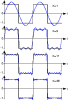
I remember once you told me that the rising edge of a square wave contains high frequencies and the falling edge contains low frequencies, or something similar. At that time, I didn't want to stir up a hornet's nest for myself so I just skipped that detail. But it seems now it's the time to enter deep waters.
You should know this from Fourier analysis. What are the Fourier coefficients for a square wave? Don't they extend up to an infinite number of harmonics of the fundamental frequency?Frequency simply means number of cycles per second. So, in simplest terms, I don't see any cycles in the rising or falling edge of a square wave. So, what does that mean?
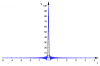
Another related detail, which is quite mystery to me, is that an impulse contains all the possible frequencies with the same amplitude (misterT also mentioned it twice in this thread). Now, an impulse is nothing more than a vertical straight line and I can't see any cycles there! If I have a graph of sine or cosine wave I can clearly see the cycles and hence frequency. This proves I can trust my eyesight but not my mind!
I hope i did not say that because it is not correct. If i did say it, then I misspoke. Basically fast edges (both rising and falling) imply high frequency content.
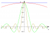
You can't see the cycles because when you add up an infinite number of sine waves with all frequencies, you get a narrow pulse. It's just a result of the math.
What do you mean by the part in bold? Kindly also have a look on **broken link removed**. By the way, I only started learning fourier series yesterday, so please don't mind if my queries are just way too silly!
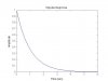
You said that this is the impulse of a RC low pass circuit. A pulse with a very high amplitude and very short duration (assume area of the pulse is unity then this approximates to a unit impulse) is applied to the terminals Vin. Doesn't the response you attached show the capacitor discharging? I think the capacitor should get charged up when a pulse is applied and the response should look like this. Please let me know where I'm having it wrong. Thanks.
I couldn't find any diagram which shows that as you add up more and more number of sine waves with increasing frequencies, the result gets closer to an ideal impulse. Could you please help? I have also searched for an applet of fourier transform but couldn't find it.
What you can try is to write a computer program that adds up lots and lots of sine waves over a wide band with very narrow spacing between the frequencies. You won't be able to make an impulse, but you should be able to at least make a narrow pulse. This won't be a square pulse, but remember that an impulse does not really have a shape to it, so what you are looking for is a function that gets narrower and narrower as you add up more and more frequencies.
The bold part means what it says, or to expand the sentence for clarity. The presence of fast edges (such as with a square wave) or sharp corners (such as with a triangle wave) implies that the signal can be resolved into frequency components that include high frequency (even infinitely high frequency). In other words, we use the idea of superposition and claim that the signal we have can be represented as a sum (even an infinite sum is allowed) of sinusoids made from the fundamental frequency and any or all harmonics of that frequency.
Thank you very much, especially for the graphs. They were very helpful.
Before proceeding with any other query I would like to clarify something you said post #16.
But whenever a periodic function is resolved into harmonics using fourier series each successive sinusoid (or, harmonic) has higher frequency than the previous one but lesser amplitude. This means that there will come a time when frequency will get infinite for the components of any function. Then, what's so special about functions such as square or triangle waves about having high frequency components? I think any function can have high frequency harmonics. I hope my query is clear. If not, then please let me. I will try to rephrase it. Thanks a lot.
Best wishes
PG