William At MyBlueRoom
New Member
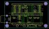
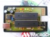
It's a beautiful looking board, what's the cost I wonder. I have a Hong Kong connection if you need to contact him. I assume that's a 18F4550 on the left.Mike said:Bill,
Sorry if I'm goin' off-topic again but I thought you might be interested in a neat layout I just stumbled upon for a USB-ICD2 clone from a chap in Hong Kong. It really looks like a decent layout for through-hole components and it includes the 74HCT125 buffers which will allow 3.3v target operation for dsPIC and PIC24 devices. I may change my USB-ICD2 layout to look a little more like this one.
BTW, I emailed this chap to ask if he'd sell me blank printed circuit boards and I'll let you know what he says.
Mike
What USB driver did you use with the 18F4550? I tried the Microchip driver but no go.
PS he's got a 16MHz xtal on the left IC, most use either 20 or 24 MHz for USB. And what's the multiturn pot for?
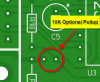
PPS I've left the error LED off my design, never seen it lit. What sort of errors is it for?
Last edited:
") There are a lot of wholes I can skip and but the pins on the socket. That will help.
There are a lot of wholes I can skip and but the pins on the socket. That will help.