Electro Tech is an online community (with over 170,000 members) who enjoy talking about and building electronic circuits, projects and gadgets. To participate you need to register. Registration is free. Click here to register now.
Welcome to our site! Electro Tech is an online community (with over 170,000 members) who enjoy talking about and building electronic circuits, projects and gadgets. To participate you need to register. Registration is free. Click here to register now.
that attempt when the IC worked for you, then no longer did not, the Transistor may have been taken out by the relay that very same time possibly because of the flyback diode not being able to properly send the inductive spike to the supply rail.
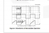
For post #80, It would be best to use an Transistor for this. It's just that with the 555Ic connected in place of the NPN Transistors Collector, the IC was sinking the relay when off, I will provide a chart that shows this.
When the IC trigger gets falling edge operation, The Trigger is sunk via the switch connected to Common GND, then the output pin 3 goes High supplying power out from the IC. then the resistor capacitor time elapses at the bottom of the chart, the output pin 3 goes low again, Sinking.
The relay coil, either can be the positive, then the other point the common, the coil is bidirectional. you can choose which one you want to be the positive.
It's just the contacts that can be an issue if the relays type is not directly known. Normally open, the relay is off until powered on. Normally closed, the relay is allowing operation when off, then when coil powered the relay is off as the contacts have opened.
Then the double throw types as well, they can be either as well, tho in either power state those can be configured for either N/O or N/C operations based on powering state.
lengths of wire and circuit traces can act as small inductors themselves, as current flows along the wire it can be pressured to an end connection point, the Diode placement puts its anode right at the coils common.
......
The Anode needs to be located at the relays left side at the Brown wire point, apologies. I will remake the image correct, please disregard image post # 90!
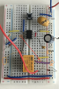
once the relay flyback diode is connected as in post #92, then the other connections show to check out.
Motor flyback diode is good, the ic is grounded, powered,
stabilized with the capacitor, the timing bank with pins 6 threshold and pin 7 discharge tied together.
Resistor R1 from power supply positive to pins 7, 6, then to capacitor.
pin 5 control cap, right.
trigger button, right.
pull up resistor for trigger pin, right.
checks out.
At the most the inductive issues would be the most to be cautious of, in the most event when the IC is directly driving the relay.
Oh and also, in the event the circuit works, and the relay and motor starts up after the button is pressed yet does not seem to want to shut down (if), then the resistor for pin 7 threshold would need the 51k resistor back in place, as the 100k would run for quite some time before shut off.
The 51k resistor and 470uF capacitor would cause the 555 to timeout in about 26 seconds. Did you measure the battery voltage while the 555 is timing and the motor is running? How low did the voltage drop?
Long winded questions and thoughts removed for shorter reading.
What would be the likely current handle for the discharge pin for an (and I would thing this can vary) 555 IC discharge pin to internal driver>
My shortened thoughts are, what of the internal 555's depicted transistor NPN from the "block diagram" being direct connected to the capacitor as the schematics per example mostly only showing small time values used thus an small cap value would not produce high risk current for the internal NPN's collector, say 10n or 100n if pulled at cap charge would allow some impressive current flow directly into the sinking method even with the resistor being quite large in impedance, unless their is an current limit within the IC itself and not displayed in the "block diagram" then I'm onto nothing then. Tho both the Fairchild and TI do not show any limiting factors per again the block diagram.
An larger microfarad, 10uF - 470uF, at charge then adequate (quick) discharge would lead to aggressive current draw and would damage the 555 discharge component potentially causing the device to state on at all times via the output.
In testing the Fairchild LM555, per 100K and 100uF cap for random time, each shut down of the LM555 pulsed my TPS2049 power switch OC indicator implying a short had minutely occurred at the LED's switch off driven by an 2N7000 FET with the 555 chip pin 3 at the FET Gates helm for direct gate control sinking the 3mm LED with 1k resistor for the LED itself, to comprehend the chips push pull ideal in my testing.
The current draw exceeded 150mA quickly before the TPS2049 switched to constant current mode and flagged the OC indicator as an pulse.
The datasheet for the LM555 has a note that says, "No protection against excessive pin 7 current is necessary providing the package dissipation rating will not be exceeded".
Yes, I was going along with the no need of current limiting via the methods of timing use, an current limit would impede the use for many potential configurations for the IC.
This datasheet for the LM555 I have dates to 2002.... reviewing the data overly.
This site uses cookies to help personalise content, tailor your experience and to keep you logged in if you register.
By continuing to use this site, you are consenting to our use of cookies.

")