Electro Tech is an online community (with over 170,000 members) who enjoy talking about and building electronic circuits, projects and gadgets. To participate you need to register. Registration is free. Click here to register now.
Welcome to our site! Electro Tech is an online community (with over 170,000 members) who enjoy talking about and building electronic circuits, projects and gadgets. To participate you need to register. Registration is free. Click here to register now.
need to reorganize the schematics and upload in diptrace preview format as per BeBe suggestion. Seems I tried this before??
OUTLINE about my bike project
Due to my changing subject on this project and my changing direction I felt a need to post an outline about what the project does, how it works, progress and why I did what I did. A working prototype is presently working except for a few add on's. Am waiting for parts to build a complete working project with enclosures as well.
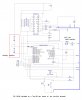
Transmitter board to date as posted is using a daughter board mounted onto a Tap-28 development board with a 18F2420 w/ ext osc.
Board utilizes a Holtek HT12E encoder. Had second thoughts about using a PIC as the encoder would work by itself but utilizing a micro-controller it allows me to incorporate a battery monitor(using PortA.0) and a piezo sounder to alert the user.. The Transmitter is un-powered until a button press to conserve battery power (need to put PIC to SLEEP to conserve more power).
Upon a switch closure, the transmitter is powered and transmits a data stream as per the HT12E.
A P-channel mosfet is included in final design to avoid any reverse polarity issues. A piezo sounder to be incorporated to alert rider.
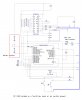
The receiver unit incorporates a PIC that controllers a 5 x 7 LED matrix that is driven by two high side drivers(TD62783APG) for each LED color(RED, GREEN) using 9v in prototype but final design to use 4.5v (need to access this as the voltage may be to low?). The circuit then utilizes a TLC5916/17 constant sink chip which is set to provide a max current draw of 26ma to each segment of the 5 x 7 Bi-color matrix.
The receiver sends the data stream to a Holtek HT12D decoder that is reset after each valid transmission to reset the data latches in the HT12D (the latches will reset upon a valid data stream as per data sheet, which is unacceptable in this application so the Vdd is toggled off then on to reset latches (tried several different configurations but to no avail).
The PIC also incorporates in final design, a battery monitor.
Preliminary tests showed a 150ma draw on the receiver board/LED matrix but experimenting with multiplexing I was able to reduce to 25ma current draw on the matrix only, as at present I need to incorporate a voltage regulator to power the PIC and the LED matrix on one battery source.
The transmitter board at first had a current draw of 8ma standby and 14ma at transmission. After utilizing a port pin to power the transmitter, the standby current draw is 5ma but hopefully by putting the pic to sleep it will lower the standby current draw.
Final design to utilize 18F25K20 pics, all smd and the 5 x 7 Kingbright LED matrix.
Got my order of 18F25K20 and 18F13K22 pics as well as found sleep.bas.
Waiting for switches then assemble a complete transmitter prototype and hopefully experiment by doing the sleep routine.
PLAN = assemble a Tap-28 development board w/o the external osc (final project will not use)board with LEDs and run the SLEEP routine to test.
Then just plug the 18F25K20 into the perf-board w/ matrix and test code with present connections.
Want to see just how low I can get the current draw down to. Found a reference to power management in the tricks and tips I think I downloaded from Microchip last year ??
Ummmm...you have a problem. The PIC18F25K20 is a 3.6V max part. Your Junebug programmer doesn't have variable Vdd, so it's not going to work to program this part. The PIC18F25K22 would be a better choice, as it will handle 5 volts max.
Also, depending on which Swordfish modules you're using, changes have to be made to some of the include modules.
I purchased a PICKIT2 several months ago and find that it works better in that it dosen't lose communication with the project like the Junebug did.
As far as Swordfish modules, I hope to not have to change any. At present only utilis and convert.
Been reading the compiler tips and tricks from microchip about power budgeting, voltage regulators etc.
I think I located some 3.6v lithium batteries that are soldered into the project (LI SOC12).
As I mentioned, on the Matrix end of things, I need 9-12v as the matrix goes dim at 4.3v while in operation and the receiver requires 2.4v so a 5v battery won't give me much "head room", that's why I am looking at 9-12v and a LDO regulator. If I go with the soldered in batteries then the P-Mosfet is replaced by the Regulator.
Utile.bas is probably not going to work. Look on that other site the ElectroMaster fears/hates for "setalldigital.bas" or something similar to that by Jerry.
You're also using shift.bas which may have issues.
The shift.bas is being used in the matrix code not the transmitter code I wrote. Will look at the setalldigital.bas.
Curious why do you feel it won't work?
And the last post about the batteries, I used the wrong battery. It was late last night and I have lots of notes and picked the wrong on.
It's no big deal setalldigital didn't work all the time anyway that why you have to set the register's your self sometimes. It took me about 1 minute to get 18f 25K20 to work after I downloaded the datasheet.
I feel it doesn't work because IT DOES NOT WORK.. The k-series chips (all) have differences from the previous 18F-series chips and were not yet developed when most of the modules were written. Primarily, there are differences in port configurations for periferals, number of UARTS, ADC channels and so on.
My discussions regarding the TAP-20 USB board using the PIC18F14K50 cover some problems you'll have with the 18F13K20.
I presume you are using the 18F25K20 to control the matrix. K-series. Likely will need changes to modules.
It's no big deal setalldigital didn't work all the time anyway that why you have to set the register's your self sometimes. It took me about 1 minute to get 18f 25K20 to work after I downloaded the datasheet.
YES I am using the 189F25K20 on the matrix board as well (need to conserve as much battery power as possiable)
Will read the issues using this pic. Need to look at the TAP20 board issue with this pic as well.
In mean time assembling a Tap 28, needed to find socket, switches etc.
I realize you don't always recognize the finer points of language, but.... the issue is not with the TAP-20 board. The issue is that the K-series PICs have changed the way certain features are implemented and/or in the peripheral configuration, so some of the Swordfish modules need modifications to work correctly on the K-series.
Yes, there is a discussion of some of these issues under the TAP-20 topics, because the TAP-20 is designed to use K-series parts.
Whats the board got to do with it? It's not the compiler, The problem is Swordfish is not keeping up with newer chips and that's that.
It's no big deal just change the setting to use what you want. Read about the ADC and Usart and make the changes pointing to the right registers. And you'll be picking in no time flat. If you get really lost and can't figure it out ask Jerry
I just might stay with the 2420 to avoid ANY issues.
I am going to see if I can get an LED to blink but it might avoid a train wreck if I stay with the 2420. COST was another factor but it might be offset by not having to use a regulator.
Going to reaccesse this. Battery choice enters the game as well.
YES I read the data sheet but need to look deeper.
I know it has nothing to do with the Tap-20 board, which I looked into for some advice on using the 18F24K20.
This site uses cookies to help personalise content, tailor your experience and to keep you logged in if you register.
By continuing to use this site, you are consenting to our use of cookies.