Continue to Site

Welcome to our site!

Electro Tech is an online community (with over 170,000 members) who enjoy talking about and building electronic circuits, projects and gadgets. To participate you need to register. Registration is free. Click here to register now.

  • Welcome to our site! Electro Tech is an online community (with over 170,000 members) who enjoy talking about and building electronic circuits, projects and gadgets. To participate you need to register. Registration is free. Click here to register now.

HT12D and HT12E encoder/decoder issues

Status
Not open for further replies.

MrDEB

Well-Known Member
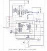
using this schematic **broken link removed** BUT am only using two data inputs instead of 4.
The circuit works but I only used a 4 pos dip switch(D0-D3) and one push button. No diodes.
Upon pressing the push button I get the receiver to respond using LEDs on all 4 outputs. The LEDs work as planed BUT they stay on too long.
Studying the schematic for the transmitter, it has 8 1n4009 diodes, D1-D4 on the data inputs and D5-D8 on the Te pin.
I get the reasoning behind the D5-D8 diodes (to isolate the TE pin from any other button presses but D1-D4 is open for discussion as to WHY?
This might by why the LEDs stay on too long on the HT12D. This is where I am headed but using 1n4148 as I have no 1n4009 ultra high speed switching diodes.
This might save someone the same issues??
 
going by the data sheet

I need to find a way to transmit a “CLEAR BIT” (an address that does nothing except transmit a different address than the address fort LEFT or RIGHT. Something to keep the TE pin low but the two data lines go high again. After a few seconds the TE line goes high again and no transmission is enabled so battery drain is minimized.
Am looking at an RC/BJT circuit or a 7555 but there has to be a better method?


Of the 212 series of decoders, the HT12F has no data
output pin but its VT pin can be used as a momentary
data output. The HT12D, on the other hand, provides 4
latch type data pins whose data remain unchanged until
new data are received.
 
maybe not so crazy of an idea -- using a port pin on the pic to power the HT12d then cycle the port from HIGH to LOW then back to HIGH to reset the HT12D.
The HT12D only draws, according to the data sheet less than 1ma?? no load
 
Checked current in standby = .1ma when the latches are enabled = 9ma
Tested by disconnecting and it appears to reset the latches as wanted. Doesn't sound to kosher of a practice but ?? have yet to come up with a better solution??
 
debuging code w/ delayms

Been cleaning up and debugging code trying to get the decoder chip HT12D to cooperate.
After hacking away I finally got it working. Couldn't figure out how it was resetting itself until I put a delayms() after disabiling the HT12D power. It was turning off then on so fast.
I know this may be a trivial subject for some but it sure showed me what was going on.
Here are the two sub routine calls but only one has the D_CODE = 0 delayms(2000)
The meter shows a loss of power indicating a reset of the HT12D latches.
I tried resetting using a transmission from the HT12E but couldn't get it to work right (the HT12D latches remain set until another data stream is received. This solves two issues - battery life as only one transmission instead of two and an easy method to reset the latches on the HT12D.
One issue I kept having issues with was where to put the D_CODE=0 statement. Tried several locations but it wouldn't toggle as desired.
Code:
     // CHECK SWITCHES
    //LEFT TURN    
        If s1 = 0 Then          // sw 1 closed
        count = 0
                  
        Repeat
        LEFT
        DelayMS(200)
        Inc(count)
        Until count=5
        D_code=0
        
       End If
         
     //RIGHT TURN   
       If s2 = 0 Then          // sw 1 closed
        count = 0
         
        Repeat
        RIGHT
        DelayMS(200)
        Inc(count)
        Until count=5
        D_code=0              //turn off decoder for reset
        delayms(2000)
       End If
 
Alternating pins ON and OFF

trying to configure how to make the ResetPin_G = 1 and ResetPin_R = 0 go from both = 1 to alternate back and forth then both on again.
The green LEDs can't be seen in broad daylight but the Red can be seen as well as orange (both RED and GREEN = LOW. Want to mix it up. Thought about toggle but it dosent mix it up right. ANY SUGGESTIONS? Contemplating a for next loop but?
Code:
 // RIDE   
       If s1=0 And s2 = 0 Then
      
       For index = 0 To Bound (Ride_Data)
        DelaymS(3)//10 500us for constant on
        X = Ride_Data(index)
 
        LE = 0
        ResetPin_R = 1   // disable OE RED
        ResetPin_G = 1  // disable OE Green
         Shift.Out(MSB_FIRST, X ,8)  
        LE = 1         //Latch data
        PORTB = R_Rows(index)  
        DelayUS(20) //20 us
        ResetPin_G = 1 // output LOW = ON HIGH = OFF
        ResetPin_R = 0  // both reset pins low = orange
        LE = 0
        
    Next


     End If
 
Implementing SLEEP in SFB

using Swordfish Basic, It was suggested to put the pic to sleep to conserve battery power.
I disabled the transmitter etc until a button is pressed. The circuit before the button press is 5ma. Upon button press = 15ma for a few seconds then back to 5ma.
How much lower will the circuit go in SLEEP mode?
THEN do I just insert WAKE to get things up and running again.
Want to try but before delving into this I figure I would get advice. Afraid if I do it wrong, the circuit would be stuck in sleep forever??
On the other end (receiver circuit which consists of a 5 x 7 led matrix, I went from 150ma draw max down to 25ma max.. Experimenting with multiplexing.
 
My bad
At the present I have the transmitter disabled until a switch is closed.
Let me find the part number on the transmitter/receiver modules. Itead sells similar as does sparkfun but part numbers are different.
Will get back to you with schematic if I cn post it(had issues w/ posting earlier this week)
 
Boy that part # is small

link to transmitter **broken link removed**

need to upload schematic to photobucket but with the transmitter disabled(no power) the circuit is drawing 5ma. If I put it to sleep I should draw less.
Tried doing a search at DIY but no connection?
Looked at SF manual etc as well as Microchip data sheet.
Looks like all I need to do is put a LEEP command then put a WAKE command when a switch is closed but I realize this may be too simplistic.
Took your advice and disconnected power to the transmitter and transmitter receives power via a port pin. Works great to this point. Got the matrix current draw down to a max of 25ma using multiplexing.
 
Whew doggie! You need an ol blood hound to follow this thingee across all the forums and topics you been posting under! A fella can't keep straight what you trying to do!

Your schematic is too blurry to read! You need to save it bigger. Thought you got a mess o help here: Posting a two page schematic
 
Here a test to see if it is possible to save a dptrace to something readable

test.PNG

Lets see. nope that's no good try one more time

Yep it can save a big view of your sch
test1.PNG
 
Last edited:
I used infa view as suggested but maybe go with a jpeg instead of a png?
I made the mistake of changing topic so I am going to write up an outline so one can follow but having second thoughts about using the PIC in the transmitter but the PIC solves several issues that I will outline in detail.
In the meantime the schematic I will re-post in a jpeg format. Hopefully Electrotech online will get the issue of attachments solved.
 
lets see if this will post

here is a png to best fit desktop as per infaview
 

Attachments

  • prototype2.jpg
    prototype2.jpg
    66.2 KB · Views: 829
Mrdeb take a look at both SCH I did both with dpTrace the LAST one it's scale-able
 
Dptrace can save it as a big image all you do is click print preview then hit save a box opens set it to 600% and save as a jpg

And you get this which is readable
test1.jpg

No need of any bull gunk to change this to that to that and post it gunk.
Post your dang files and I'll show you how it would look done with only dptrace.
 
Last edited:
Status
Not open for further replies.

New Articles From Microcontroller Tips

Back
Top