Electro Tech is an online community (with over 170,000 members) who enjoy talking about and building electronic circuits, projects and gadgets. To participate you need to register. Registration is free. Click here to register now.
Welcome to our site! Electro Tech is an online community (with over 170,000 members) who enjoy talking about and building electronic circuits, projects and gadgets. To participate you need to register. Registration is free. Click here to register now.
The datasheet for the TSOP1738 shows a filter capacitor connected between pin 1 and 2. The datasheet explains that the 38kHz IR must be modulated on and off in bursts with certain gaps between the bursts so that the AGC can reduce the gain to avoid interference from compact fluorescent light bulbs that produce continuous 38kHz IR.
Here is the datasheet:
As AG says, it's ESSENTIAL to have a decoupling capacitor from pin 1 to pin 2, a 47uF or similar will be fine - keeps leads as short as possible, poor layout (and no capacitor) will make it unstable.
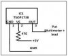
I would also suggest a pullup resistor from output to +5V, as per my tutorial hardware:
You also need a scope to check it, a multimeter is no use - connect a scope to the output and point an IR remote control at the TSOP, when you press a button you should see the modulation signal.
You can use a logic probe if you dont have a 'scope.
I have had instability issues with this device, I've salvaged a few and they usually have a 100r resistor and large electro filtering the supply to them.
Use a tv remote to test the device, one that you know works.
You can do a quick test on a tv remote by looking at it with the cam on your mobile, most of them are sensistive to infra red.
A TSOP1738 works at 38kHz. A problem testing it with a TV remote is that the remote might work on a different frequency like 56kHz then the sensitivity of the TSOP1738 will be very low.
I should start the physical build tonite or tomorrow. I'll be able to advise on how it goes for the OP.
I am running a 39.2Khz PWM, 50% DC as the common anode carrier (8Mhz PIC clk, I could OSCTUNE for exactly 38Khz) and I am using a 500 uSec interrupt to alternate (50% DC) IR emitter pulse bursts from 2 PIC pins by pulling to ground. I am going direct from the PIC pins to the IR emitters so I will have to current limit @ under 25mA. If the range isn't sufficient I'll have to add transistor drives for more TX current. I need about 3' range.
Nigel: I see your tut page mentions a IR driver transistor. What is the current pulse that you use?
Tearing apart handheld remotes often reveals a 455 KHz ceramic resonator used as the clock for a small microprocessor: 455/12 = 37.91 KHz.
Using 455KHz as your clock would make a lot of the calculating drop out of the program, as well as lower the power drastically.
Well I got the TSOp working etc. BUT the AGC makes it very hard to calibrate a reflective trigger for objects passing by the TX & RX. Gotta get a TSOP without the AGC I guess.
Well I got the TSOp working etc. BUT the AGC makes it very hard to calibrate a reflective trigger for objects passing by the TX & RX. Gotta get a TSOP without the AGC I guess.
The TSOP IR receiver ICs are used for remote control inside a home where there are probably some compact fluorescent light bulbs continuously producing 38kHz IR. They are not used for detecting passing objects.
You can make your own simple photo sensor circuit with a photo-transistor and an opamp.
The new TSSP IR receiver ICs are not the old TSOP remote control ICs. They do not require the 38kHz to be modulated with bursts then will have interference from visible light, heat and other IR systems.
The bandpass of 38kHz (other frequencies are available) IR receiver ICs is centered at 38kHz and the circuit is most sensitive at 38kHz. The bandpass is not very narrow so they still have some sensitivity at other frequencies and can receive interference from them.
The new TSSP IR receiver ICs reduce their sensitivity to visible light but can receive interference from it. Sunlight has lots of strong IR which can overload their photo-diode. Compact fluorescent light bulbs produce lots of 38kHz IR which can also overload them.
But the old TSOP receiver ICs have AGC which reduces interference.
This site uses cookies to help personalise content, tailor your experience and to keep you logged in if you register.
By continuing to use this site, you are consenting to our use of cookies.