Electro Tech is an online community (with over 170,000 members) who enjoy talking about and building electronic circuits, projects and gadgets. To participate you need to register. Registration is free. Click here to register now.
Welcome to our site! Electro Tech is an online community (with over 170,000 members) who enjoy talking about and building electronic circuits, projects and gadgets. To participate you need to register. Registration is free. Click here to register now.
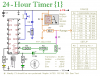
Timer to run for ever.
Timer to repeat every 24 hours.
Relay to be on for 3 hours.
Remove D1. (make...run for ever)
Add MC14073 or CD4073 (CMOS 3 input AND) OR (CMOS 3 input NAND will also work)
Connect the three inputs to Q12, Q13 and Q14.
Connect unused inputs to GND, VSS, VE (all the same thing)
Output of AND gate to R7. The AND will be high 1/8 of the time or 3 hours out of 24.
hi alec thanks for your help i will try and tell you if any problem occurs ok............
and friend ronsimpson are you satisfied with alec.... and thanks for your help also..... here in this circuit diagram where should i connect analogue timer clock sounder terminals... and please friend ronsimpson ... kindly give a good circuit detail....
The circuit in post #19 may need a further mod to cope with two alarm clocks driving the reset pin, because of one clock loading the other. Attached is my suggestion (it just adds 2 resistors), which biases the transistor base ~0.3V below the +ve rail to improve sensitivity.
Hi allec..Ok friend thanks for your kind help.. And the timer switch you have given here is not avaible in india.. Here the time switch is very costly and i have seen a cheap time switch which is £53.92 on the site which you gaven.. But this time switch is not avaible in india. And i hope this one is best according to price for indian.. Well friend if i use your circuit will it work properly and reliably for years..
That's not cheap! I didn't notice one at that price. The cheapest one, which I drew to your attention, was just over £2 !! A pity you can't get such a thing locally in India.
Hello alec i am sorry the price was 3.92 not 53.92 it was misstyping.. And alec assume that I have use alarm clock which is working on 1.2v pencil cell and circuit is same as you have defined.. And all other are same as in my circuit diagram.. Now.. What do you say will it work reliably for years...
I've just tested the simulation with clocks sending out alarm pulses as low as 1V peak-to-peak at 500Hz and the resulting reset pulse trains look fine. Good luck with the build. Bear in mind that if the timer range etc is set to 2hrs as per post #21 then manually resetting the timer by pushbutton will give a 2hr timed period, whereas alarm signals lasting 1hr will give a 1hr + 2hr = 3hr timed period. If that's a problem we'll need to rethink the auto-reset circuit. It would help if we knew exactly what sort of signal (voltage, polarity, frequency, duration) is available to you when the alarm sounds.
ok friend thanks............... Thank youuuuuuuuuuuuuuuuuuuuuuuuuuuuuuuuuuuuuuuuuuuuuuuuuuuuuuuuuuuuuuuuuuuuuuuuuu very much for a great help...
You have also helped in my water sensor post.... I am very very thankfull to you.....
I will test this circuit and then I will reply you... ok... please stay connected to me... friend......
Please send your email id in private message to me so that If it tooks time to build me this project then I can contact you....
As you haven't provided details of the alarm clock output signals I've re-designed the reset circuit to cope with a wider input range. The attached circuit will respond to either pulsed DC or sine-wave signals of amplitude as low as 0.2V and as high as 5V, and now includes a set/reset latch (made from cross-coupled NAND gates) so that the first-arriving pulse/sine signal sets the latch and resets the timer IC at pin 12. Subsequent timer-reset pulses are ignored until the latch is reset. This means that the timer can be configured for 3hrs, regardless of whether it is triggered by an alarm clock or by the button. The latch requires a reset pulse at > 1hr (if the alarm sounds for 1hr). It can conveniently be obtained at 1.5Hrs by using the timer output Qn-1, where Qn is the Range output used to give the 3hr output. For example, if you use timer pin 2 (Q13) to give the 3hr output then pin 1 (Q12) will provide the 1.5hr output for resetting the latch. If this new circuit proves too sensitive the sensitivity can be reduced by reducing R4.
hi alec.... please define IC pins I couldn't understand " U1a , U1b etc" please tell the Ic pins numbers instead of " U1a , U1b etc..." and I have CD4060 Ic... I dont have CD4093 so please tell on CD4060.....
I have attach here so please tell how do I reset here.......
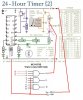
You need a CD4093B in addition to your CD4060.
Attached is how my reset circuit is connected to the CD4060.
I have added the pin numbers of the 4093. Note that because the 4060 does not have a Q11 output we are using Q12 and Q13 (pins 1 and 2). This has made it necessary to change C3 from 10uF to 4.7uF so that you get your required 3hr time-out. All the figures in the Range Table should, therefore, be divided by two. Note also that C2 is now 1nF and is not connected to the V+ rail.
Friend thanks for your reply. And can you tell me how will this circuit work with alarm clock.And for gaining 3hr time what changes will i have to do.Because i can't understand chart properly..
As I said above, the circuit will respond to either pulsed DC or sine-wave signals of amplitude as low as 0.2V and as high as 5V. Something in that range is likely to be available at the alarm sounder teminals. If you use the suggested circuit with the connections as shown you will only have to adjust the pot to set the 3hr time (the pot should give a time range of 2-6 hrs).
so alec.... it means the circuit you have suggested will give 3 hour time... and assume to have 2 hour time what we should so...
I mean how do we calculate this by table shown it circuit and after calculating how to setup correctly...
please explain with example.... I will be very appreciate...
If you want a 2hr time then just adjust the pot (R4). You can forget the table: the post #34 circuit has already taken that into account and is set up correctly for any time you choose in the range 2-6hrs. Re-read post #36 !!
Ok friend thanks ..... but as you said "If you want a 2hr time then just adjust the pot (R4). "
But how much does we adjust to get 2hr....
and another thing if I want 1hr , 2hr , 3hr, 4 hr... etc times then how do I calculate and adjust the pot(R4)....
I mean that how do we remove value according to required time and set R4.
Is there any formula.....
If your alarm clock beeps continuously for 1hr then you won't be able to use my suggested circuit for set times less than 2hrs (because the timer would be re-triggered after 1/2 hr).
There is no formula for the time period.
This site uses cookies to help personalise content, tailor your experience and to keep you logged in if you register.
By continuing to use this site, you are consenting to our use of cookies.

")